


Only the carrier frequency is varied in interruption-free, typically sawtooth or triangular sweeps. A sweep period is called a chirp. Depending on the given requirement, individual ramps with different frequency change rates (chirp rates) can be played out one after the other. This makes it possible to optimise the radar in terms of range resolution, radial velocity resolution and working range.
For generating signals, a Voltage-Controlled Oscillator (VCO) is modulated and the output signal is brought to the desired bandwidth and into the desired band using multipliers and frequency converters (Fig. 1).
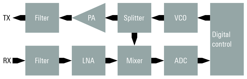 Fig. 1: Simplified block diagram of an FMCW radar. The received signal is mixed with the signal being transmitted. Only the resulting, relatively narrowband beat frequency is digitised and analysed.
The signal received by the sensor exhibits a frequency offset (proportional to the target distance) to the momentary transmit frequency, which has moved up a bit on the sweep ramp during the signal delay. If the relative velocities of the transmitter and receiver differ, there is also a Doppler shift (Fig. 2). The transmit and receive signals are mixed to a relatively low intermediate frequency that can be directly sampled.
The advantage of this method is the very inexpensive components. No wideband ADCs or DACs are needed. And thanks to the extremely low data rates, the digital signal processing requirements are not so demanding. But the requirements on analog components at the transmitting end are all the more stringent. Deviations from the linearity of the FM ramps lead directly to a poorer signal-to-noise ratio (which means objects might be overlooked) or to phantom signals (simulation of objects that are not really there).
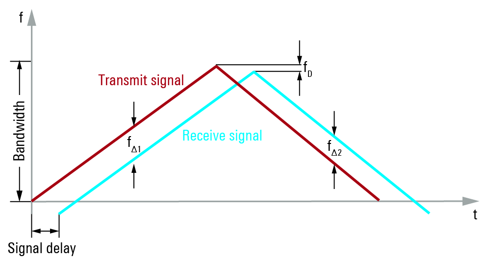 Fig. 2: FMCW signal with triangular modulation. To simply determine the distance, either a rising or falling edge would suffice (sawtooth); in both cases the target distance is proportional to the frequency difference fΔ, but distorted by the Doppler frequency fD when the radar and target are moving relative to each other. The graphic shows the case where an object is moving away. If you want to determine the relative velocity based on the Doppler frequency and also eliminate the Doppler distance error, you need both edges. In that case, the Doppler frequency is half the difference of the frequency differences fΔ1 and fΔ2. To achieve the desired precision, high requirements are placed on the linearity of the edges – and consequently on the measuring equipment used during radar development.
Demand for wideband signal analysis
Since higher bandwidths are associated with higher range resolution, FMCW radars are designed to be as wideband as possible at the analogue transmitting and receiving ends. In the E band (76GHz to 77GHz or 77GHz to 81GHz), up to 4GHz of contiguous spectrum is available, resulting in a range resolution of about 7cm.
In research and development, as well as during validation, the complete signal must be known over the entire modulation bandwidth. Until recently, only oscilloscopes offered the necessary analysis bandwidths of up to 4GHz.
Validating conformity with ETSI, FCC, etc., requires not only signal analysis but also spectral measurements using a spectrum analyser in order to detect spurious emissions and measure the occupied bandwidth.
The R&SFSW signal and spectrum analyser combines these two functions.
New bandwidth options on the analyser equip the instrument with analysis bandwidths of 4,4GHz, 6.4GHz and 8.3GHz, respectively.
These bandwidths are unique in signal and spectrum analysis. The advantage over a combination solution with an oscilloscope (for wideband IF sampling) is clear: a single instrument analyses all frequency ranges of interest and digitises them with a high dynamic range.
This applies to signals modulated on an intermediate frequency, to the transmit signal in the E band and to the low-frequency receive signal mixed with the transmit signal. The top-of-the-line model, the R&SFSW85, additionally provides a very high quality spectrum analyser that covers the range from 2Hz to 85GHz in a single sweep and features an internal attenuator, preselection and image suppression (Fig. 3).
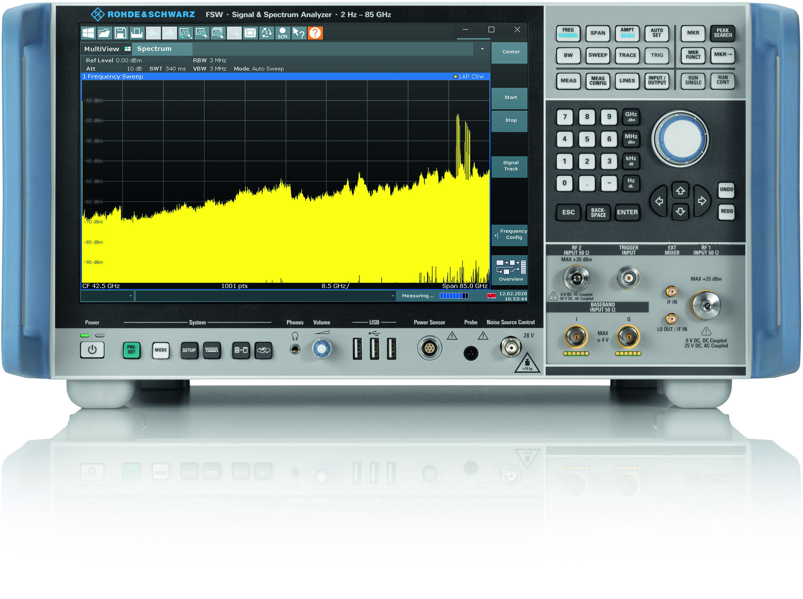 Fig. 3: The R&S FSW85 covers the entire spectrum in a single sweep with preselection from 2Hz to 85GHz. The 4GHz radar signal in the E band at 79GHz is clearly visible.
Customised measurement application
The signal data recorded by the analyser in wideband is initially available in digital format. All of the signal information, i.e. level and phase or frequency, is contained within the analysis bandwidth, acquisition period and dynamic range.
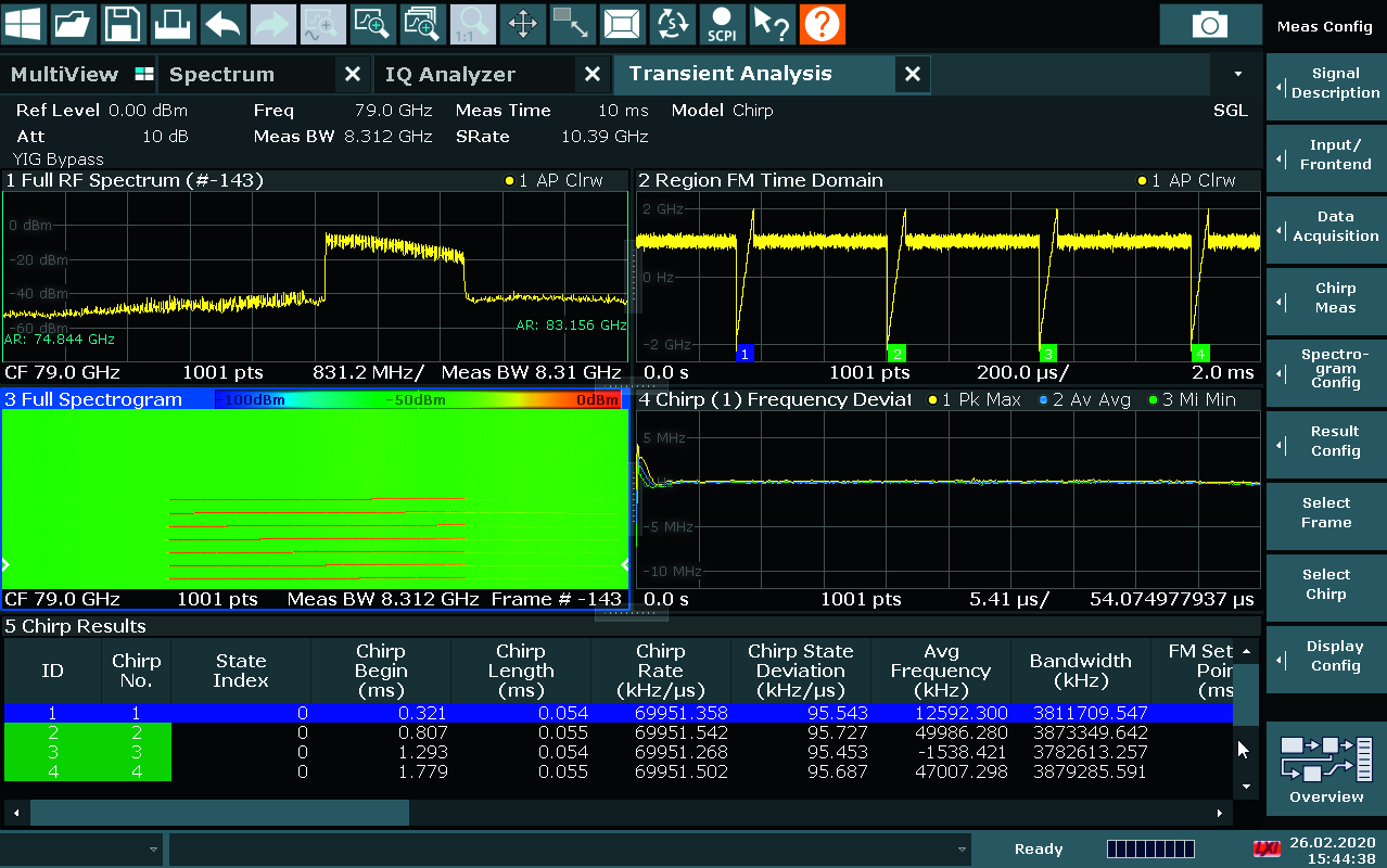
Rohde & Schwarz provides different measurement applications for analysing this information. The R&SFSW-K60 transient analysis option with its R&SFSW-K60c chirp analysis extension is specifically designed for the FMCW signals used in automotive radar.
The software selectively searches for FM transients in the acquisition memory, recognses and catalogs them and displays them in a table with their key parameters (Fig. 4). Individual chirps in the acquisition memory can be selectively chosen and analysed. Statistical analysis across a large number of acquisitions is also possible.
Key parameters are the chirp length, chirp rate and the settling time. Nonlinearities in the frequency modulation, i.e. in the time domain, as well as frequency deviations from the ideal frequency are calculated, graphically displayed and statistically evaluated.
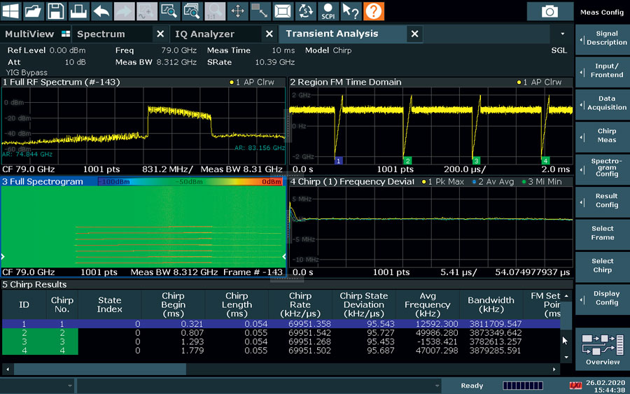 Fig. 4: The R&S FSW-K60 transient analysis software option extended by the R&S FSW-K60c chirp analysis option provides all key parameters of an FMCW signal on one screen.
Interference problems are increasing
With the trend toward higher signal bandwidths and the ever growing number of radar sensors installed in vehicles, interference problems are increasing: radar sensors receive signals from neighboring vehicles, which limits their functionality and can even cause connected driver assistance systems to make wrong decisions. Additional frequency bands and waveforms can solve these problems.
Regulatory authorities are therefore considering releasing frequencies beyond 100GHz for automotive radars, e.g. the 134 GHz to 141 GHz band. Within the 7 GHz available here, a 4 GHz sensor could hop to an interference-free frequency subrange when interference occurs.
Technologies such as software defined radar make it possible to use entirely different waveforms, for instance the Orthogonal Frequency Division multiplexing (OFDM) modulation used with LTE and 5G. Using different types of modulation on the individual transceiver channels would allow the MIMO multi-antenna technology to be used even more effectively, as demonstrated by Uhnder with its RoC. And individual parameters could be modulated onto the separate radar signals, allowing the receive signal to be clearly identified.
With up to 8.3GHz analysis bandwidth and a large number of measurement applications, the R&S FSW is ready for whatever direction technology takes.