


Exhaust ventilation fans eliminate humidity, odours and airborne particulates from bathrooms, closets, mudrooms, laundry, workout space, and other places in residential and business buildings. Ventilation fans improve indoor air quality by venting unwanted humid, and stale air outside quickly, which helps to control mould and mildew growth. For ease of use and automation, modern exhaust fans have built-in timers and humidity sensors.
The analysed fan contains two ICs (a programmable timer and a quad operational amplifier) and more than 50 discreet components. The use of the SLG46811 reduces the number of components significantly and thus decreases the device price. Figure 1 shows a general schematic of the device based on the SLG46811.

Figure 1. General schematic of exhaust fan with timer and humidity sensor based on SLG46811
1. GreenPAK design
Figure 2 shows an internal design of the exhaust fan in the Go Configure Software Hub. The complete design file can be found here: Exhaust Fan with Timer and Humidity Sensor.gp6.
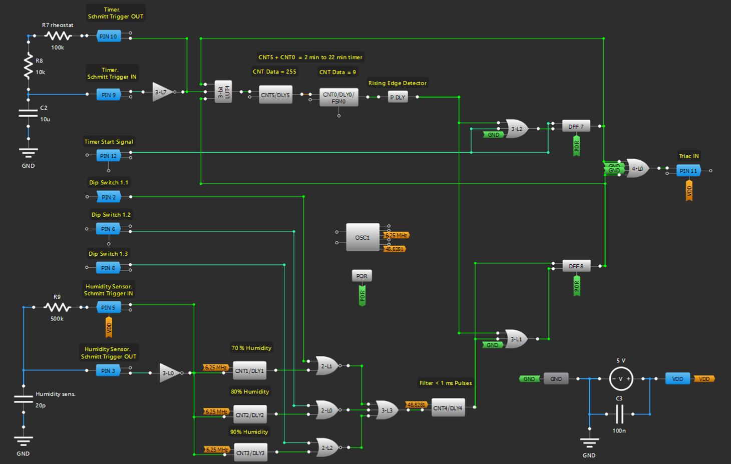
Figure 2. Exhaust fan with timer and humiditysensorGreenPAK designer schematic
1.1 Power supply circuit
The power supply circuit of the analysed fanwas used. This circuit wassimplified by removing several components, since to power the SLG46811only 5V is required (see Figure 1), and the analysed fan required two supply voltages of 10V and 5V.
The fan, in addition to the mains voltage, also needs a signal to start the timer. This signal uses the same mains voltage, which is supplied through a separate push button.
Resistors R1, R2, and R3 with Zener diode ZD1 and diode D1 form 5V supply voltage for the SLG46811.
Furthermore, a circuit to transform the mains voltage for the timer to the voltage level applicable for the SLG46811 pins was used. Resistors R4, R5, and R6 are dropping resistors. Zener diode ZD2 limits the positive half-wave of the signal at 5.6V and diode D2 clips the negative half-wave of the signal. The output of this circuit is a 5V square wave signal with the frequency of the mains.
1.2 Off-delay timer
Pins 9 and 10, 3-bit LUT7 (an inverter), capacitor С2, rheostat R7, and resistor R8 form a Schmitt trigger oscillator. Depending on the position of R7’s wiper, the total resistance of R7 and R8 changes from 10 kΩ to 110 kΩ, and accordingly, the frequency also changes by a factor of 11. This allows the digital counter to set desired timer’s off-delay time in the range from two to 22 minutes by setting a corresponding counter data.
When the user presses a wall push button S2 (or pulls a pull cord switch), a series of pulses go to the DFF7 input D, and the same pulsesgo through the 3-bit LUT2 (OR gate) to the CLK input. The first pulse causes a high-level signal on the DFF output and thus passes the Schmitt trigger oscillator’s square wave signal to the CNT5 CLK input and provides the high-level signal on the 4-bit LUT0 output to start the fan (see Figure 3). The CNT5 and the CNT1 are chained together to get the desired counter time data to 2295. When the counter ends counting,a high-level voltage appears on its output. After passing through the Rising Edge Detector and the OR gate, this signal will be on the CLK input of the DFF7. The DFF output goes LOW on the triggering edge of the pulse and the counter stops counting.
Because the output voltage level of the CNT0 remainsHIGH until the next pulse on its clock input, the Rising Edge Detector makes the signal levelLOWon the DFF’s CLK input after the counter has counted till the end and the DFF output then goes LOW. Without the Rising Edge Detector, the next time after the buttonis pressed, it will be impossible to ensure a rising edge signal for the DFF7.
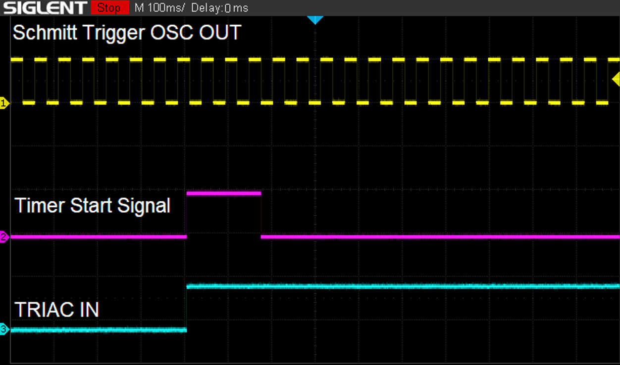
Figure 3. Waveforms foroff-delay timer part
1.3 Humidity sensor
Pins 5 and 3, 3-bit LUT0 (an inverter), a humidity sensor, and resistor R9form the second Schmitt trigger oscillator. The frequency of the oscillator depends on air humidity. In this project, a capacitive humidity sensor was used. Its frequency decreases with increasing humidity. CNT/DLY0, CNT/DLY1, and CNT/DLY2 were used as Frequency Detectors for three different frequencies 42kHz, 35kHz, and 28kHz, respectively.Thus, they are configured to detect three different humidity levels (70%, 80%, and 90%).The user can use the DIP switch to set the desired humidity level at which the fan will start. Please note that the Frequency Detectorsthresholds should be set for a particular sensor individually.
Due to the slight instability of the oscillator’s frequency, a HIGH level does not appearat the 3-bit LUT3 (OR gate) outputimmediately.At first, it will be turned off and on chaotically nearby a threshold level. A 1ms CNT/DLY4 (in a delay mode) filters these unwanted spikes.
The high-level signal on the CNT/DLY4 output causes the high-level signal on the DFF8 output and thus passes the Schmitt trigger oscillator’s square wave signal to the CNT5 CLK input and provides the high-level signal on the 4-bit LUT0 output to start the fan. When the counter ends counting, the Rising Edge Detector provides a pulse to the DFF8, and on its rising edge, the DFF8 output goes LOW if the humidity drops below the set threshold level or remains HIGH and starts the timer one more time.
Figure 4 shows waveforms for humidity control part.
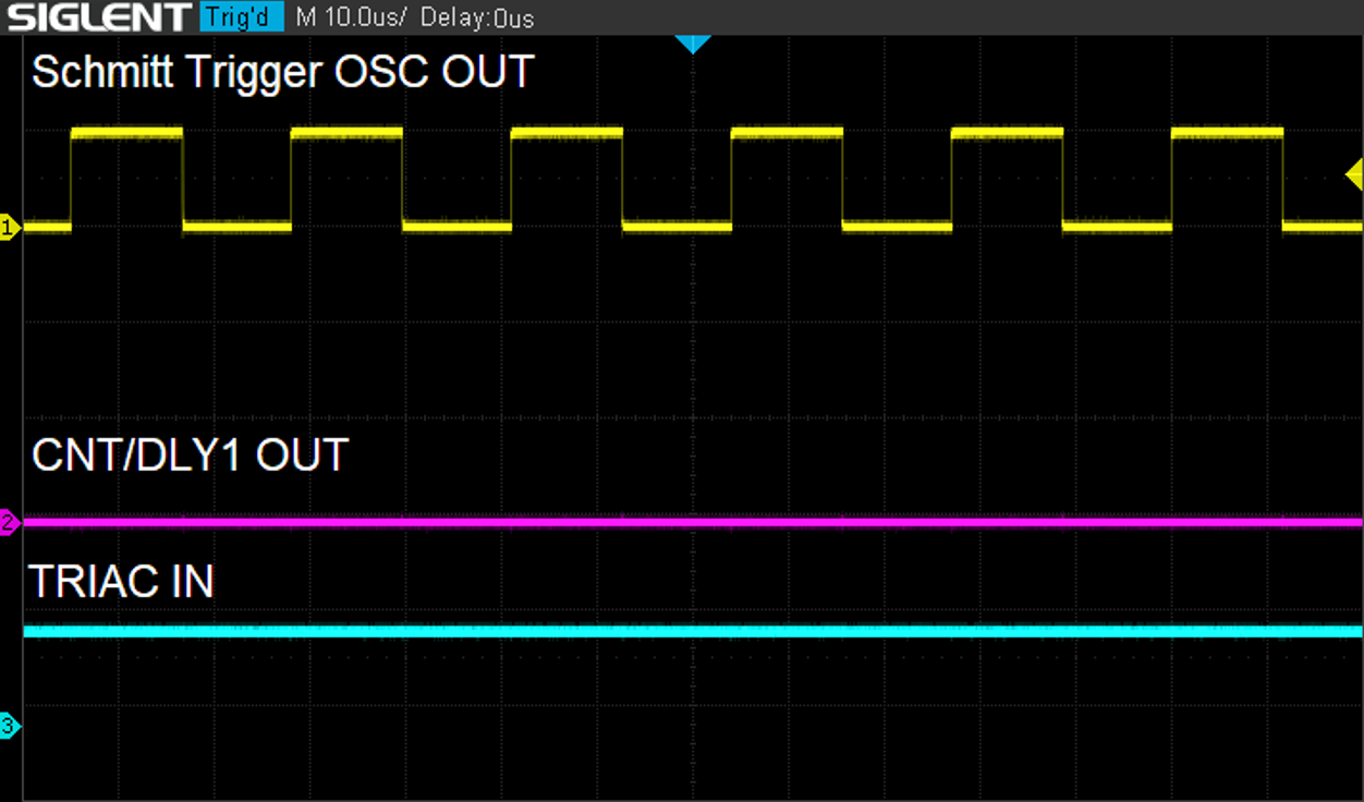
Figure 4. Waveforms for humidity control part
1.4 Motor control
Usually, in the exhaust fans, an asynchronous motor with a shaded pole is used. To control the asynchronous motor, a triac with a gate trigger current equal to 3mAwas used. This triac is driven by the SLG46811. Resistor R9 limits the triac input current. To prevent the motor from overheating, a thermal fuse was used.
2. Simulation of the project
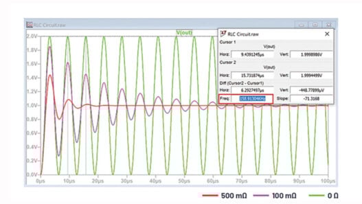
The project can be simulated in the GreenPAK Designer Software Simulation Tool. All external components are availablein the GreenPAK Designer, except for the humidity sensor, which can be easily replaced with a capacitor. Figure 5 shows simulation waveforms for both Schmitt trigger oscillators.
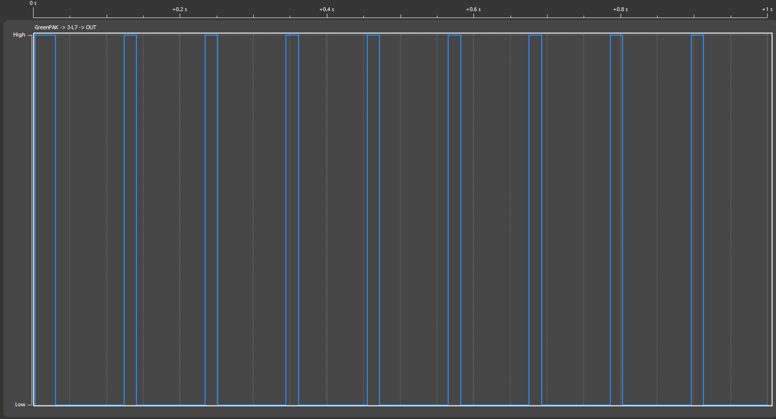

Figure 5. Simulation waveforms showing work of exhaust fan’s Schmitt trigger oscillators
Conclusions
In this article, we analysed a typical cheap exhaust fan with an off-delay timer and a humidity sensor. Its design was re-created using SLG46811. This GreenPAK IC has space- and cost-saving features. The use of the SLG46811 allows reducing of more than 30 components from PCB, including two ICs, and thus decreases the device price. Furthermore, we also achieved a reduction of the power consumption.