


It is also important to consider the type of output signal needed. This can depend on factors such as the type of device connected to the encoder output, the operating voltage of the connected device and the length and characteristics of the physical connection between the two.
The most common types of encoder outputs are open-collector, push-pull, and differential line driver. Let’s take a closer look at these to understand how to choose the right type for any given application.
Design choice at the physical layer
The encoder itself may be an incremental type with a quadrature output, a commutation encoder with a motor-pole output or the output may be a serial protocol. This discussion focuses on the physical layer, and we can see that the output digital signal swings between high and low logic levels with each type of encoder. If the device operates from a 5V supply, the output will swing between 0V, or ground, representing logic zero, and 5V representing logic 1 (figure 1). An incremental encoder output, for example, is a basic square wave.

Figure 1. Typical 5V digital square wave
The open-collector output is extremely common among rotary encoders. This type of output is so named because the collector pin of the output transistor is connected directly to an external pin (figure 2) and is not connected to any other circuitry, such as a passive pull-up resistor, inside the device. The output can be driven to ground to signify logic 0, or when the output signal should be logic 1 or high, the transistor is simply left open or disconnected.
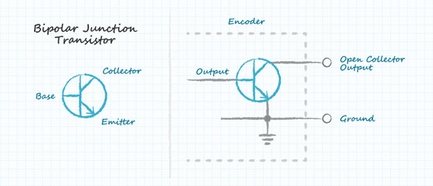
Figure 2. Simplified open-collector output schematic
To ensure the connected device can detect the output state reliably, whether this is intended to be logic 0 or 1, an external pull-up resistor is needed (figure 3). When the output is required to be low, the output transistor is turned on and the collector potential moves down towards ground.
If the output is required to be high, the transistor base current is turned off and the pull-up resistor pulls the collector potential up to the rail. The collector can be pulled up to a voltage rail lower or higher than the encoder’s operating voltage, which gives designers flexibility to connect systems that operate from different supply voltages.
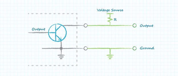
Figure 3. An external pull-up resistor is needed to ensure reliable signaling
Despite this extra flexibility, the open-collector output has some disadvantages. The pull-up resistor introduces I2R losses (power consumed over the resistor) and contributes to an RC time constant in combination with circuit capacitances such as the transistor parasitic capacitance, effectively slowing the transitions between logic states. Instead of transitioning instantaneously, logic states change in a finite time (figure 4).
The slope of the transition, or slew rate, limits the operating speed of the encoder; a lower slew rate reduces the operating speed, or reduces the resolution in the case of an incremental encoder. The slew rate can be increased with a stronger pull-up, by using a lower resistance value, but this draws a higher current when the output is low thereby increasing power consumption.

Figure 4. Logic-signal transition time limited by slew rate
The push-pull output
A push-pull output circuit comprising two transistors can overcome the disadvantages of the open-collector interface. One transistor is connected between the output and ground, as in the open-collector circuit, while the second transistor is connected between the output and the power rail to perform as an active pull-up (figure 5).
This configuration can achieve faster slew rates than using resistors and the active pull-up dissipates less power. As a result, the push-pull output is better suited to energy-conscious applications such as battery-powered equipment.
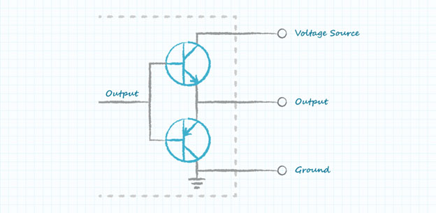
Figure 5. Push-pull output schematic
Push-pull outputs are featured on all of CUI Devices’ single-ended AMT encoders. Other devices can be connected easily to their outputs without requiring external pull-ups, which simplifies testing and prototyping. The datasheets for AMT encoders refer to the output as CMOS, which indicates how connected devices should interpret the signals presented. The actual voltage levels may vary between devices, so it is always recommended to check the datasheet when specifying components.
Differential output for noisy environments
Although a push-pull encoder offers greater speed and lower power consumption than an otherwise-comparable open-collector device, the single-ended output is not always the best choice for some applications. If the output signals must be transmitted over long cable distances, or if the operating environment contains large quantities of electrical noise and interference, a differential output can offer better performance.
When signals are transmitted from a single-ended output, the receiver references the signal to a common ground. Errors can occur when the signal is transmitted over long cables, as the voltage drop can be large and cable capacitance decreases the slew rate.
Differential signaling helps avoid this problem. To create a differential output, two transistors are configured in a similar way to the push-pull circuit, but the output comprises two signals instead of a signal and ground. One of these signals (signal A, see figure 6) matches the original encoder output, while the other (A-) is its exact opposite. As such, this opposite signal is often referred to as a complementary signal. The two together are known as a differential pair.
When this pair of signals is transmitted over the cable, the receiver references the two signals to each other instead of referencing one signal to ground. Hence, instead of responding to specific voltage levels as being high or low relative to ground, the receiver looks at the voltage difference between the two signals. The magnitude of the difference is twice that of the original signal relative to ground, which makes the differential signal less susceptible to errors in the presence of noise or interference.
The differential receiver reconstructs the pair of signals into a single-ended signal at the voltage levels required by the host system. Using differential transceivers also allows devices supplied by different voltage rails to work together without suffering the signal-degradation challenges encountered when using a single-ended device in an application with long cable distances.
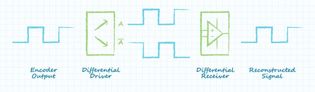
Figure 6. The differential driver generates complementary signals that are reconstructed by the receiver
In addition to causing signal degradation over long cable distances, noise can be coupled onto the cables and then enter the electrical system. The noise on the cables is seen as voltages of varying magnitudes, which can cause the receiving side of a system to read high and low logic signals incorrectly and so introduce errors in the data from the encoder. Differential line driver interfaces can prevent such errors and are recommended for cable lengths over one metre.
Twisted-pair cabling is required for use with differential line drivers. The two conductors carrying A and A- signals are intertwined and contain a specific number of turns within a given distance. This ensures that any noise coupled onto one wire is immediately also applied on the other. Because the differential receiver subtracts the received signals from each other, any noise present simultaneously on the A and A- wires is cancelled (figure 7).
This capability is called common-mode rejection and makes differential line-driver interfaces a popular choice in industrial and automotive applications.

Figure 7. The differential receiver ignores noise present on both signals
Engineers can choose the right encoder for a given application by analysing the devices available on the market and understanding the relative strengths and weaknesses of the different types. CUI Devices’ AMT encoders with push-pull outputs simplify installation in a wide variety of applications and help engineers minimise the application’s power consumption. CUI Devices also offers a selection of devices with differential line driver outputs for use in electrically noisy environments or over long transmission distances.
Helpful resources
View CUI Devices’ entire line of AMT modular encoders
Interested in more encoder related topics? Click here for additional posts