


With electronics controlling an ever-higher percentage of vehicle functions, electrical power control is transitioning from mechanical relays, solenoids and switches to devices like IGBTs, MOSFETs, Schottky diodes and thyristors. Though doubts have been raised about the short-circuit robustness of SiC MOSFETs, recent research shows that current offering can provide sufficient robustness for off-board electronic vehicle (EV) applications like DC fast charging stations.
A combination of powerful forces is spurring changes in circuit protection, power control and sensing applications in the automotive industry. These include, but are not limited to the trend for one wire/one fuse protection, higher power consumption, improving space and weight efficiency, smarter circuit protection, infotainment systems, safety features (such as multiple airbags, battery disconnect controls, passenger sensing system, auto-dimming mirrors, stability control, seat belt pre-tensioning and tyre pressure monitoring, demand for higher performance and lower emissions and the rise of hybrid, electric and alternative fuel vehicles
 Figure 1: Short circuit test results for different device
This is accompanied by the demand for highly efficient power semiconductors for electric and hybrid vehicles applications. It makes sense to use the advantages of silicon carbide (SiC) over conventional silicon chips in automotive applications, for example off-board EV chargers. The higher efficiency and power density of SiC enables higher ranges or smaller batteries, reduced system dimensions and faster charging times.
SiC MOSFETs are promising candidates for power converters, e.g. in battery charging applications, due to their significantly lower switching losses compared to silicon (Si) IGBTs. There were doubts to be addressed about SiC MOSFET performance under short-circuit conditions. Their higher short-circuit current density and lower thermal capacitance mean SiC MOSFETs have a lower short-circuit withstand time than Si IGBTs. With a proper gate drive design, this can be sufficiently resolved.
Short-circuit robustness
Under short-circuit conditions, SiC MOSFETs have a current density five to 10 times higher than similarly rated Si IGBTs. The higher instantaneous power density and lower thermal capacitance lead to a faster and higher rise in temperature, and therefore a lower short-circuit withstand time. The MOSFET saturation current is primarily controlled by the design of the channel area. A shorter channel and a higher gate voltage when switched on are conducive to reducing turn-on resistance. However, they also increase the saturation current and reduce short-circuit robustness.
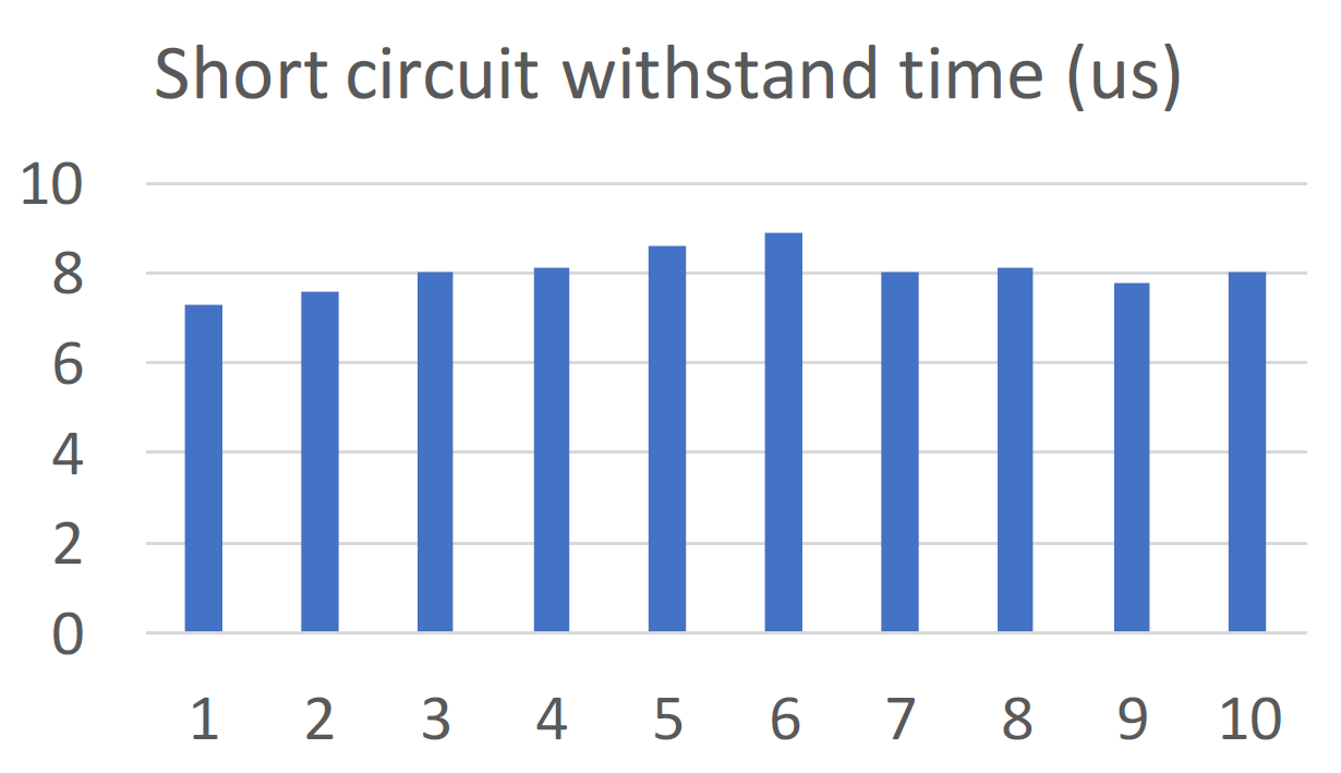 Figure 2: Short-circuit time below 600V DC
This compromise between on-state resistance and short-circuit current density is inherent to the SiC MOSFET design and cannot be adjusted without adversely affecting performance. Developing gate drives with faster response times than conventional IGBT drives addresses the concerns of short-circuit robustness and enables SiC MOSFETs to maintain their operating characteristics under normal conditions as well as enable a safety protocol that protects the device and surrounding circuit during a short-circuit event.
Destructive short-circuit tests
To test whether this also works in practice, a test circuit was developed using passive high-voltage probes with high bandwidth to measure the voltage of drain to source (Vds) and gate to source (Vgs). A Rogowski coil measured the device current (Id). With this test arrangement, the short-circuit robustness of a 1,200V, 80mΩ SiC MOSFET (the LSIC1MO120E0080 from Littelfuse) was tested under various operating conditions.
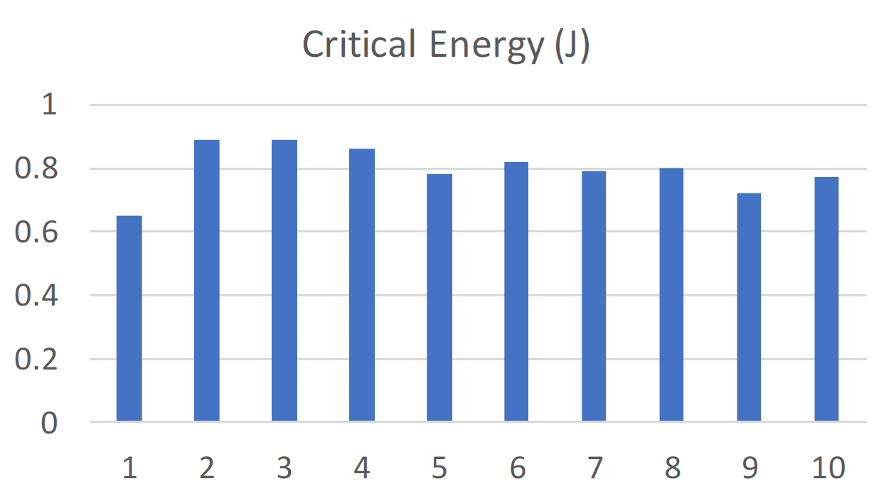 Figure 3: Critical Energy Below 600V DC
The results of 10 samples with 600V drain voltage and 20V gate voltage at room temperature is shown in Figure 1. Figure 2 and Figure 3 show the short-circuit robustness and the critical energy for destructive failure. The devices have a narrow distribution with a short-circuit peak current of about 250A and a short-circuit withstand time of more than 7µs. Figure 4 shows the short-circuit test results at various drain voltages from 200 to 800V at a gate voltage of 20V. While the peak current is similar for each test, the short-circuit withstand time is reduced from more than 20µs at 200V drain voltage to 3.6µs at 800V.
 Figure 4: Short-circuit current supply at different gate voltages
Figure 4 shows the test results with different gate voltages of 15V and 20V at a drain voltage of 600V. The peak current is highly dependent on the gate voltage, which decreases from 250A at 20V to 100A at 15V. The short-circuit withstand time at 15V gate voltage is longer than 10µs. The recommended gate voltage for this MOSFET is 20V to minimise the device’s on-state resistance. The short-circuit withstand time was proven to be approximately 7µs at 600V drain voltage and 3.6µs at 800V. A longer short-circuit time can be achieved by using a lower bus voltage or a lower gate voltage. However, both approaches could impair the design of a power converter.
Using a gate driver
A better approach is to use a fast responding gate driver that can detect a short-circuit and shut down the MOSFET before it is damaged. Several standard ICs for Si IGBT devices are available with integrated over-voltage protection. This function monitors Vds in the switched-on state and switches off devices in the event of over-current. The same driver ICs can be used for SiC MOSFET short-circuit protection if the response time is fast enough. Figure 6 shows the implementation scheme, where DD should block the Vds when switched off. DC should protect the DE-SAT pin during the switching transition and CB should control the blanking time to avoid false tripping during switching transients.
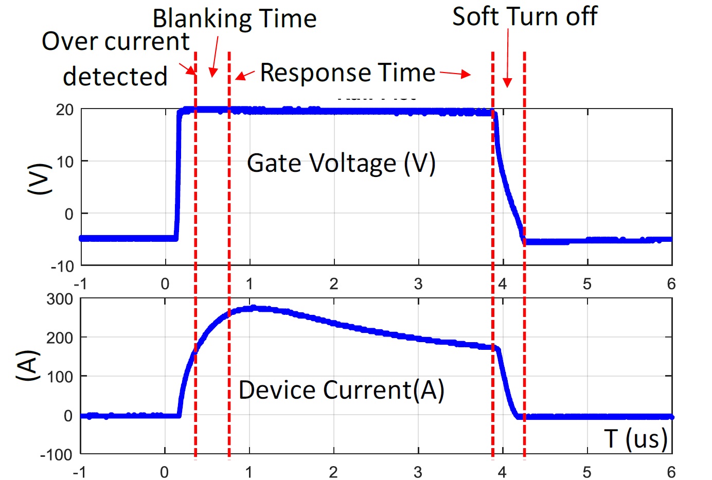
Figure 5: Short circuit current and response time with active VCE (SAT) monitoring
Figure 5 shows the short-circuit transients with activated IC over-voltage protection. Due to the high switching speed and optimised circuit layout required in SiC-based designs, the blanking time can be significantly shorter than with IGBT circuits. For SiC devices, CB is typically selected with less than 100pF and the blanking time can be as low as 200ns to reduce the driver IC’s overall response time and protect the SiC MOSFETs. According to the results, each of the three ICs that were tested can protect the SiC MOSFET within one to 4µs during shoot-through. They also provide functions for slow turn-off under short-circuit conditions to protect MOSFETs and driver ICs.
Half-bridge configuration
The MOSFETs were tested under short-circuit conditions in both single device and half-bridge configurations with the gate driver IC that exhibited the slowest response time. With the half-bridge, the upper device remains switched on throughout the entire transient and the lower device is driven by a gate driver with an over-voltage function.
The results show that the MOSFET can be safely switched off under both conditions. The DC link voltage in the half-bridge is shared by both devices and the actual voltage per device is considerably lower than that of the DC bus voltage. This offers more margin for the protective circuit’s reaction time. If both the lower and upper devices provide protection functions, each can protect the entire circuit.
The study shows that the short-circuit peak current and withstand time of 1,200V, 80mΩ SiC MOSFETs are heavily dependent on drain voltage and gate voltage, but independent of housing temperature and switching speed. Commercial IGBT drivers with over-voltage protection can effectively protect SiC MOSFETs, with proper circuit design and integration techniques under real short-circuit conditions, both with a single device and in half-bridge configuration.