


The input stage can be as simple as a rectifier off an AC line input voltage or it may be a Power Factor Correction (PFC) circuit which generates a constant high voltage DC. The DC-link capacitor acts as the PFC stage output filter, absorbing switching currents for minimum ripple voltage. The output stage could be a switched mode converter or inverter taking bursts of high frequency current from the DC-link capacitor.
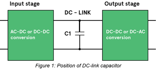
The capacitor has to be sized to meet specifications for ripple voltage at the DC-link and energy storage between mains cycles or when input power is lost. This means it should have a low Equivalent Series Resistance (ESR) and a minimum capacitance and ripple current rating. These specifications have to be met at the required operating voltage, temperature, power output, line and switching frequencies, and target lifetime.
For low power AC/DC converters with no PFC stage, minimum capacitance is normally set by the allowed mains ripple voltage on the DC-link. This gives a capacitance value of approximately 2µF/W for a universal mains input supply. For higher power AC/DC converters with PFC, the value is set by ‘hold-up’ or ‘ride-through’ time on input power loss and a much lower capacitance is possible with energy stored at high voltage, values of less than 1µF/watt being normal.
Capacitance required for hold-up is simply calculated by equating the energy required by the load during hold-up;
th x Po/η (hold-up time times output power divided by efficiency)
with the energy difference in the capacitor between its starting voltage and final voltage at which the converter stops operating to specification;
(0.5 CV2start – 0.5 CV2finish )
This rearranges to give C = 2 Po th/ η (Vstart2 – Vfinish2)
For AC output inverters, hold-up may not be an issue and a minimum capacitance is just needed to be low enough impedance at the inverter switching frequency to minimise voltage ripple.
In practical circuits, the ripple current that the capacitor must handle without overheating by dissipation in the ESR is often the overriding factor. The current can be so high that for a given voltage, a minimum physical size of capacitor is required to achieve low ESR, high dissipation and long lifetime. This often leads to a capacitance which is well over the minimum from line ripple or hold-up calculations. The ripple current waveform is very difficult to predict as it is a combination of line frequency and input and output stage frequencies and their harmonics. The wave shapes depend on the topologies of the stages and can vary from triangular, high-rms currents in discontinuous mode PFC stages to more square-shaped currents from following bridge converter or inverter stages. The input and output stage currents are sunk and sourced respectively from the capacitor and are not necessarily in phase or at fixed frequency, complicating matters further. There are schemes however where the input and output stages can be synchronised to achieve some ripple current cancellation in the capacitor.
From calculation, experiment or simulation, headline capacitor specifications can be found but then practical considerations of size, cost, lifetime and reliability matter. A designer will see that there are several types of capacitor which are available for the application, splitting between aluminium electrolytic, film and ceramic types. The choice is not easy to make and depends strongly on the application but the general trade-off is that electrolytics are cheaper and smaller than film and ceramic types for a given combination of voltage rating and capacitance (CV ratio) but have lower ripple current rating. They also have higher variation of capacitance, ESR and ripple current rating with time and temperature and have a shorter lifetime, heavily dependent on temperature and applied voltage. Electrolytics are only available up to about 600VDC rating compared with several kV for film types, requiring series connection of electrolytics with balancing networks in high voltage applications.
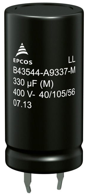
The initial cost of an electrolytic can be very much less than that of a film type with the equivalent CV ratio. Examples would be the B43544 series electrolytic and BMKP 3277 series film types from TDK EPCOS. At 470/480 µF 450V, the film type ESR is about sixty times lower, the ripple current about nine times higher and the life about four times longer at similar temperatures and frequencies. However, the electrolytic is ten times smaller and about one tenth of the cost.
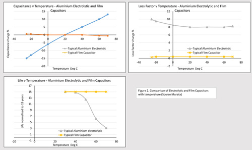
Table 1 gives a summary of the main specifications of the two examples. Perhaps more important is the way the specifications of the two types vary with the environment and application conditions. Figure 2 shows how the capacitance, loss factor and life of typical electrolytic and film capacitors vary with temperature. End of life of a capacitor is defined as degradation of performance down to a particular level, typically a variation of capacitance of greater than 20% from initial value, a dissipation factor change of more than 1.3 times initial value or leakage current greater than initial specified limit. If this cannot be tolerated and the component is used at high temperature, it may be necessary to change it out many times during the life of the end equipment with the associated purchasing, rework and down-time costs.
| TDK EPCOS | B43544B5477M0*# | B32778J4487K000 |
| Type | Electrolytic | Metallised polypropylene film |
| Capacitance | 470 µF | 480 µF |
| Voltage rating maximum working | 450 VDC | 450 VDC |
| ESR typical at 10 kHz 70°C | 63 mohms | 0.9 mohm |
| I rms max at 105°C, 10 kHz | 3.7 A | 31.8 A |
| Size (mm) | 35 (D) x 45 (L) | 130.0 x 58.0 x 57.5 |
| Volume (cm2) | 43 | 433 |
| Lifetime at 85°C, Vrated and Irated | 12,000 hours | 50,000 hours |
| Normalised cost in high quantity | 1 | 10 |
Table 1: Comparison of example TDK EPCOS aluminium electrolytic and film capacitors
There is clearly a major difference in life time between the two types but during the expected life of an electrolytic capacitor, its inherent reliability is actually not too different to film or ceramic types. TDK -EPCOS quotes 10 FITS (failures in 109 operating hours) at 0.5 Vrated and 40°C for the example film capacitor and although the company does not quote a figure for the electrolytic in its data sheet, typical field failure rates of 0.5 to 20 FITs have been reported for electrolytics in general. Under voltage stress, film types do have the advantage that they are to an extent self-healing and can take higher surge voltages than electrolytics.
Ceramic DC-link capacitors such as the CeraLinkTM range from TDK EPCOS are only available currently up to capacitances of about 20µF at 500V (part B58033I5206M001) but if 23 were paralleled to achieve a comparable 460 µF at 192 cm3, they would promise potentially huge ripple current handling. Each one is rated at 31.5A at 100kHz, 85°C so 23 together would handle a staggering theoretical 724A. Like with other ceramic capacitors, however, the capacitance and ESR value does vary strongly with applied voltage and temperature.
To summarise, the choice of capacitor type is very dependent on the application, and electrolytics are still a very good option when cost is sensitive and the environment is not harsh. When temperatures and ripple currents are high, opting for an electrolytic instead of film can be a false economy when considering the costs of a shorter life leading to expensive replacement and down time. TDK EPCOS has a wide choice of both capacitor types suited for harsh conditions and in various mounting formats.
Click here for more information.