


This article originally appeared in the Feb’23 magazine issue of Electronic Specifier Design – see ES’s Magazine Archives for more featured publications.
Applications such as ADAS, infotainment, virtual reality, pedestrian and gesture recognition are driving demand for high performance SoCs. They require a variety of precision supply voltages that are subject to precise sequencing to start or shut down the processor. A system’s volatile and non-volatile memories and any peripherals also require additional power supplies that must be included in the processor’s power up and power down sequence. All this has to be implemented in a limited space.
A PMIC-based solution optimises supply voltage for the SoC and customises handshake and interface architectures to shorten the development cycle. There is however little or no flexibility to adapt to other SoCs and thermal issues; power supplies are limited to a specific SoC and its immediate environment. As power supply requirements change, a redesign is often required
Decentralised power
A decentralised power strategy, adopted by Rohm, enables PMICs with a different number of voltage regulators to be optimised for an application. It also allows several PMICs to be interconnected and operate as a single unit. These decentralised power supplies enable driver MOS stages to support high output currents for the processor’s computational.
To be able to cover vehicle safety requirements, critical components/ functions have to be duplicated and methods for possible failure detection have to be implemented. These redundancy requirements and monitoring features drive up system costs but integrating functional safety features into PMICs reduces system costs (see Figure 1).
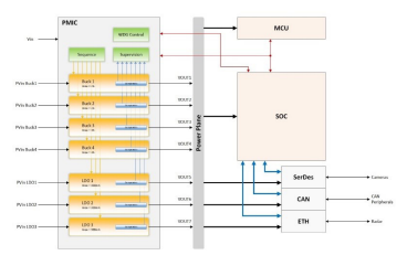 Figure 1. Sensor Fusion with Rohm’s safety PMIC.
The BD96801xxx-C is a configurable PMIC for processors, SoCs, FPGAs and applications with high safety requirements. It features seven scalable voltage regulators housed in a UQFN48 package (6.0 x 6.0 x 1.0mm). It requires an input voltage of 2.7 to 5.5V and provides output voltages with accuracy of ±1.2%. It is designed in accordance with ISO26262(2018.3), is AECQ100-qualified and operates at -40 to +125°C.
It integrates power supplies for the application processors/SoCs, DDR memory and common system I/Os (four switching regulators with output voltages from 0.5 to 3.3V and three LDOs with voltages from 0.3 to 3.3V each and 0.3A output). Buck regulators 1/2 provide output currents of up to 2.0 and 10/20A, respectively, via external driver MOS stages. Buck regulators 3/4 provide output currents up to 4.0A. Buck regulators 1/2 and buck regulators 3/4 can be operated in two-phase mode for double current. Switching regulator frequency is 2.25 or 4.0MHz.
A programmable power control sequencer can support applications and use cases and is expandable to multiple PMICs and many operating parameters configurable by OTP and/or programmable by software. Remote differential sensing for each individual switching regulator keeps the voltages at the load stable and counteracts voltage drops on the PCBs.
For safety there is configurable over- and under-voltage protection, monitoring of the maximum current of the regulators and detection of short circuits, as well as configurable thresholds to notify the processor of output voltage abnormalities. There is also two-stage thermal monitoring with self-protection shutdown, two redundant voltage references and self-monitored dual clocking, as well as analogue and digital BIST functions. The I2C interface between the PMIC and the MCU allows flexible, simple control of the PMIC registers and information exchange of the protection and diagnostic functions, which can be secured via a CRC code.
To maximise flexibility, Buck1 and Buck2 can be wired individually or operated in two-phase mode. For higher current requirements, an external MosDriver (10 or 20A) can be connected for one or both buck controllers.
Without an external driver module, a maximum of two 2A output currents or one 4A in two-phase operation can be obtained. Alternatively, depending on the choice of the external driver IC, output currents of 10 or 20A in single phase operation deliver a peak value of 15 and 30A respectively
Other combinations could be equipping Buck1 with a driver and Buck2 without, for one 10A (20A) and one 2A output currents. Maximum currents are achieved in two-phase operation and with the external connection of both bucks with one driver IC each.
Buck3 and Buck4 are not designed for connection to an external Mos driver IC, so they can be connected individually for up to 4A output current each or both can be connected in two-phase mode for a maximum 8A output.
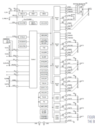
Figure 2. Block diagram of the BD96801xxx-C