Mining a rich seam to reduce bulk capacitor size
By combining two capacitors of different voltages, the MinE-CAP controller reduces volume in high density designs, says Christophe Basso, Business Development Manager, Future Electronics.
This article originally appeared in the May '22 magazine issue of Electronic Specifier Design – see ES's Magazine Archives for more featured publications.

A capacitor can be selected based on electrical or physical parameters but voltage and operating temperature are of utmost importance. As the temperature approaches the maximum specified in the datasheet, a derating factor must be respected to obtain the longest operating lifetime. It is not uncommon to see derating factors approaching 30% of the maximum voltage for aluminium electrolytic types with a recommendation to increase this safety margin as the part heats up.
For example, travel adapters, when operated at the lowest input (85V rms), the rectified voltage peaks at 120V and can increase up to 180V in North America (127V rms). In a European outlet, the mains can be as high as 265V rms (the maximum of the nominal 230V rms specification) and biases the bulk capacitor at a 375V level. Designers chose a bulk capacitor according to the highest input voltage and therefore 400V types are popular.
Considering a nominal high line operating voltage of 325V (230V rms nominal), it brings a derating factor of 19% for the capacitor in normal operating conditions. Capacitor temperature is affected by the rms current flowing in the component and the ambient temperature in which it operates. The rms current must be assessed in the worst-case condition. A designer can analytically compute the current or rely on simulation to assess the rms content of the current.
With a 33% voltage ripple, the valley voltage reaches 70V and this value is used for sizing the 60W converter. Past the in-rush surge, the rms current stabilises around 1.1A. In this simple setup, the current is made of 100 or 120Hz cycles but does not include the high frequency pulses representative of the downstream converter signature.

These pulses will also heat up the capacitor and must be accounted for in the evaluation process. Depending on the operating temperature, the maximum allowable rms current significantly changes and using the capacitor below its maximum temperature allows more current (see Table 1 above). Similarly, with ripple frequency the worst case corresponds to the lowest frequency.
The high-frequency pulses absorbed by a converter should have a lesser impact than the 100 or 120Hz ripple (see Table 2 below). A thermistor to limit the inrush current when the converter is plugged in will further increase the system’s board footprint. Increasing the source to 230V rms, the capacitor current drops to 585mA, making the capacitor oversized. A 30% voltage ripple reduces the effective capacitance to 68 or 47µF.

A big capacitor is required to accept the large rms current at low line but also needs to be sized for a 400V operation where the rms constraint is less important. Why not change the capacitor value in relationship with the mains input? This is the idea behind Power Integrations’ MinE-CAP controller: select a slim 400V type with a low rms capability for the high line operation and parallel a larger size, 160V-rated capacitor when the adapter operates at low line.
At the first power-on sequence, the high voltage capacitor is immediately charged but limits the in-rush current owing to its low value. The controller senses the input level and understands whether it is in high- or low-line operation. If it is high line, then a signal is sent to the downstream power supply controller which immediately starts switching.
At the same time, the controller starts slowly charging the second capacitor with a constant-current source until it reaches 145V typically. The voltage across the capacitor is regulated by the controller. When the adapter voltage drops to a lower input voltage, the controller waits until the voltage across the main capacitor matches before engaging the paralleling process to avoid a current spike.
Should the input voltage rise and pass a pre-determined threshold, then the low-line capacitor would be safely disengaged and brought back to the trickle-charge mode. If the first power-on sequence occurs at low line the low-line capacitor is charged at a faster current and once all voltages are within the expected window, the downstream switching converter starts operations.
Start-up time is typically 250ms from the initial AC connection. If the high-line capacitor connects directly to the bridge rectifier, the low level capacitor goes through the internal MinE-CAP switch. This transistor is affected by a typical RDS(on) of 620mW at the highest operating junction. It is important to verify that the rms current from the low voltage capacitor complies with the maximum power the package can dissipate while maintaining junction temperature.
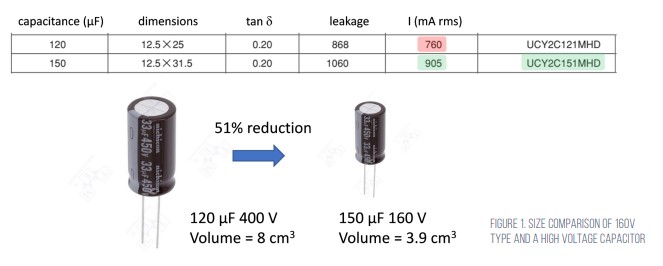
A design example To determine the front end capacitance for a 65W adapter operated on universal mains, down to 85V rms and considering a 42% ripple and valley voltage down to 70V, the capacitance is calculated to 112µF, normalised to 120µF. Nichicon has three potential candidates from the UCY series when operated below 105°C.
The volume of these 400V aluminium capacitors lies around 8cm³ to 9mm³ (0.49 to 0.55 cubic inches) and could support the entire input voltage span alone. Restricting the search to 160V types only and considering margin for the rms current, a 150µF type could also be used. This offers a volume reduction of 51%.
For the second, lower capacitance device, running at a 195V rms input corresponding to the low level of the 230V nominal voltage, the rms current is evaluated at 551mA. A 22µF capacitor will reduce the valley voltage to around 180V, which is acceptable for the downstream converter. Using a single high voltage part with two capacitors covering different voltage ranges achieves a total volume reduction of 30%.

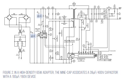
The MinE-CAP controller is designed for use with Power Integrations’ InnoSwitch3-PRO switcher. Figure 2 (above) shows a high density 65W adapter where the MinE-CAP associates a 39-µF/400-V capacitor with a lower voltage 100µF/160V device. MinE-CAP and InnoSwitch share a common Vcc rail set by a Zener-based regulator. An auxiliary winding delivers the raw DC voltage.
When operating conditions are ready, MinE-CAP enables the adapter by biasing the brown-out pin of the InnoSwitch circuit and the adapter can deliver one of the four output voltages between 5.0 and 20V.


