


When my daughter was first learning to drive, I was surprised that the driving the car itself did not seem a concern, it was other drivers; she complained how they would be close to the rear bumper, didn’t use signal indicators, and that they would cut in front of her to exit.
Autonomous autonomous vehicles will not necessarily have a human driver behind the wheel using the control mechanisms. Instead, computer code will run on the equivalent of a minimainframe computer connected to an array of sensors both inside and outside the vehicle. They will be connected to the cloud and can essentially simulate the external environment around the vehicle in real time so that they can anticipate what actions must be taken based on the current traffic conditions. This will be done regardless of the range and scope of climatic, environmental, and traffic conditions.
Arizona is one of the few places in the United States where it is legal to test autonomous vehicles without keeping a human in the driver’s seat to take over when necessary. A pedestrian was killed in the state, by a test, self-driving SUV. Although a bicycle was at the scene of the accident, it is thought the pedestrian was pushing the bike and crossing the street outside of a crosswalk. There was a human occupant behind the wheel of the SUV, but not in control of the vehicle. This incident does not inspire the public with confidence in the self-drivingcapabilities of autonomous vehicles.
The timeline to self-driving cars
There can be no doubt that self-driving cars are coming, even if there are a few setbacks along the way. According to the automotive industry, there are two standard terms for this transition: an evolutionary one where existing cars get there little by little (analogous to Tesla’s autopilot feature) and a revolutionary one where we have totally self-driving cars (like the ones Google are working on). The transition is likely to be a symbiotic amalgamation of the two approaches.
Advances likely to be made include advanced driver assistance features that will be synchronised to navigation and GPS systems. It is also likely that companies, like Google, will gather and accumulate data about every situation a self-driving vehicle might encounter. Another advance will be that 3D mapping data of major cities will need to be intensified by the mapping companies.
It is likely that there will be close collaboration between car makers and high tech auto systems providers to ensure that light detection, lidar, radar sensors, GPS, and cameras work cohesively together.
Finally, vehicles incorporating these features must be tested in all terrains and climates.
Looking further ahead, say to 2020, vehicles equipped with the semi-autonomous features outlined above should be able to navigatethrough intersections, traffic lights, and stop-and-go traffic conditions. Nevertheless, even these highly autonomous cars will still require a human being to be up front in case of emergency situations. Further ahead still, say 2024, these semi-autonomous vehicles will also function normally in more stringent conditions, such as severe weather and night time. By this timeframe, lift-service providers may start using these types of cars without any driver. Of course, vehicle makers will have to make sure their vehicles understand human signals from pedestrians, like waving them on at a crossing or intersection. All of these advances will necessitate manufacturers having many autonomous features in their vehicles, which could potentially allow for autonomous self-driving cars to be on the roads by the mid-2030s.
Automotive ICs
All the advances needed to make this timeline a reality will be a boon to the IC semiconductor industry, since it will supply the majority of the silicon content for the many systems needed to make it all happen. This silicon content will be made up of both digital and analogue ICs.
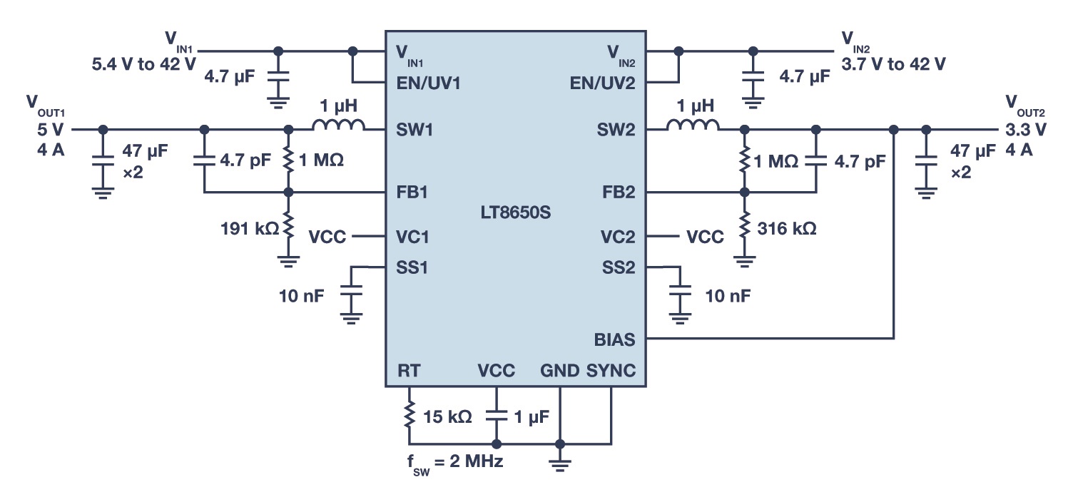 Figure 1: Simplified LT8650S schematic delivering 5V at 4A and 3.3V at 4A outputs, at 2MHz
Fully autonomous cars will clearly have many electronic systems with a mix of both digital and analogue ICs. Examples of these are advanced driver assistance systems (ADAS), automated driving computers, autonomous parking assist, blind spot monitoring, intelligent cruise control, night vision and lidar. All require a variety of voltage rails and current levels. They can however, be required to be powered directly from the automobile’s battery and/or alternator and, in some instances, from a post-regulated rail from one of these rails. This is usually the case for the core voltages of VLSI digital ICs such as FPGAs and GPUs that can need operating voltages sub-1V at currents from a couple of amps to 10s of amps.
System designers must also ensure that the ADAS complies with noise immunity standards within the vehicle. In an automotive environment, switching regulators are replacing linear regulators in areas where low heat dissipation and efficiency are valued. Moreover, the switching regulator is typically the first active component on the input power bus line and therefore has a significant impact on the EMI performance of the complete converter circuit.
There are two types of EMI emissions: conducted and radiated. Conducted emissions ride on the wires and traces that connect up to a product. Since the noise is localised to a specific terminal or connector in the design, compliance with conducted emissions requirements can often be assured relatively early in the development process with a good layout or filter design as already stated.
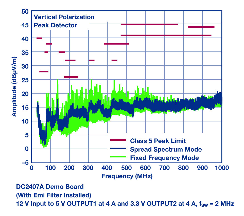 Figure 2: Radiated EMI performance for the LT8650S
Radiated emissions however are another story. Everything on the board that carries current radiates an electromagnetic field. Every trace on the board is an antenna and every copper plane is a resonator. Anything other than a pure sine wave or DC voltage generates noise all over the signal spectrum. Even with careful design, a power supply designer never really knows how bad the radiated emissions are going to be until the system gets tested, and radiated emissions testing cannot be formally performed until the design is essentially complete.
Filters are often used to reduce EMI by attenuating the strength at a certain frequency or over a range of frequencies. A portion of this energy that travels through space (radiated) is attenuated by adding metallic and magnetic shields. The part that rides on PCB traces (conducted) is tamed by adding ferrite beads and other filters. EMI cannot be eliminated, but can be attenuated to a level that is acceptable by other communication and digital components. Moreover, several regulatory bodies enforce standards to ensure compliance.
High voltage converters
It was because of these application constraints that Analog Devices developed the LT8650S, a high input voltage capable, dual output monolithic synchronous buck converter that also has low EMI/EMC emissions (see Figure 1). Its 3.0 to 42V input voltage range makes it suitable for automotive applications, including ADAS, which must regulate through cold crank and stop-start scenarios with minimum input voltages as low as 3V and load dump transients in excess of 40V. The dual-channel design consists of two high voltage 4A channels, delivering voltages as low as 0.8V, enabling it to drive the lowest voltage microprocessor cores currently available. Its synchronous rectification topology delivers up to 94.4% efficiency at a switching frequency of 2MHz, while Burst Mode operation keeps quiescent current under 6.2µA (both channels on) in no-load standby conditions, suitable for always-on systems.
Switching frequency can be programmed from 300kHz to 3MHz and synchronised throughout this range. The 40ns minimum on-time enables 16VIN to 2.0VOUT step-down conversions on the high voltage channels with a 2MHz switching frequency. Silent Switcher 2 architecture uses two internal input capacitors as well as internal BST and INTVCC capacitors to minimise the area of the hot loops. Combined with controlled switching edges and an internal construction with an integral ground plane and the use of copper pillars in lieu of bond wires, the LT8650’s design reduces EMI/EMC emissions (see Figure 2).
Low EMI emissions
For developers needing a wider input range, the company also developed the LT8645S, a high input voltage capable monolithic synchronous buck converter that also has low EMI emissions. Its 3.4 to 65V input voltage range makes it suitable for both automotive and truck applications that must regulate through cold crank and stop-start scenarios with minimum input voltages as low as 3.4V and load dump transients more than 60V. Figure 3 shows the single channel design delivering an 8A output at 5V. Its synchronous rectification topology delivers up to 94% efficiency at a switching frequency of 2 MHz, while Burst Mode operation keeps quiescent current under 2.5µA in no-load standby conditions, for always-on systems.
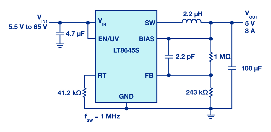 Figure 3: Simplified LT8645S schematic
The switching frequency can be programmed from 200kHz to 2.2MHz and synchronised throughout this range. Silent Switcher 2 architecture uses two internal input capacitors, as well as internal BST and INTVCC capacitors to minimise the area of the hot loops. Controlled switching edges and an internal construction with an integral ground plane and the use of copper pillars in lieu of bond wires, reduce EMI/EMC emissions (see Figure 4 for emissions output characteristics).
For both converters, the EMI/EMC performance is not sensitive to board layout, which simplifies design and reducing risk even when using two-layer PC boards. The converters pass the automotive CISPR 25, Class 5 peak EMI limits. Spread spectrum frequency modulation is also available to lower EMI levels further.
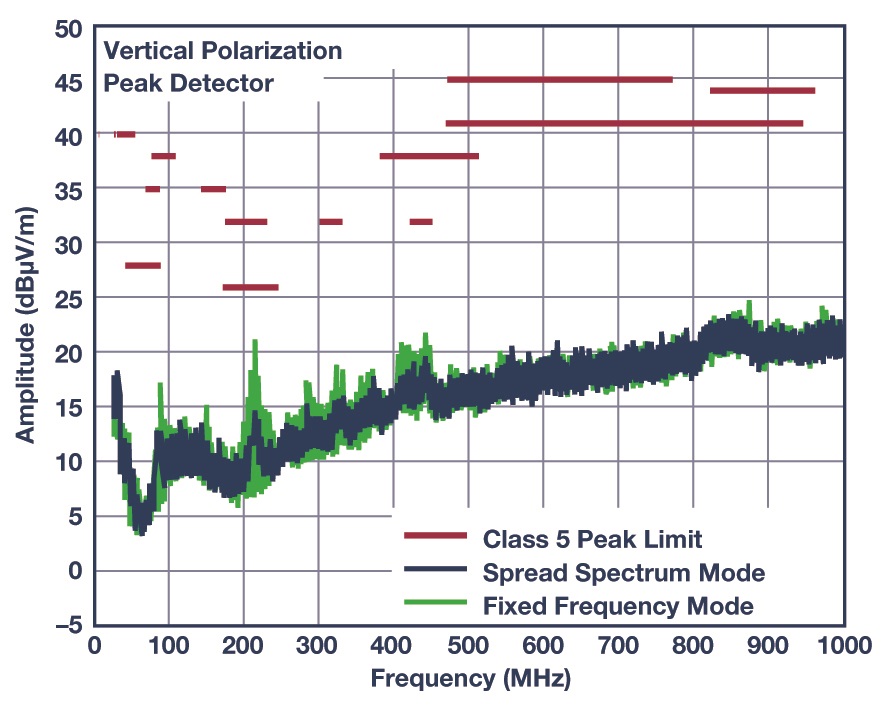 Figure 4: Radiated EMI performance graph for the LT8645S
Internal top and bottom high efficiency power switches are integrated in a single die, with boost diode, oscillator, control, and logic circuitry. Low ripple Burst Mode operation maintains high efficiency at low output currents while keeping output ripple below 10mV p-p.
The LT8650S is packaged in a small, thermally enhanced 4.0 x 6.0mm IC pin LGA package and the LT8645S is in a small thermally enhanced 4.0 x 6.0mm IC 32-lead LQFN package.