


N+1 redundant power module connection guarantees reliable system availability even if a power supply fails. However, the common use of decoupling diodes in such modules causes a large voltage drop leading to high power losses generating heat.
After a complete design review, PULS is replacing these diodes with high-efficiency MOSFETs, adding useful features for system designers.
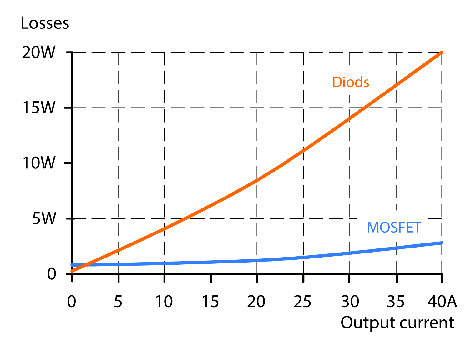
Figure 1: Conventional diode decoupling shows 40A load creates losses of approximately 20W
In a redundant system, two or more power supplies are connected in parallel and decoupled by one or more redundancy modules. The module prevents short-circuiting of the bus voltage if a short-circuit occurs in the output side of a power supply. To achieve this, a diode or equivalent component is used for decoupling. One is sufficient for each power supply. The disadvantage of this diode decoupling is significant power loss in the form of heat
For example, a load current of 40A creates approximately 20W of power losses (Figure 1). This creates heavy thermally induced stress for the power electronics, which can only be reduced by means of large heat sinks.
Optimal redundancy
When analysing the results, it quickly became clear that standard epitaxial or Schottky diodes could not fulfil the need for minimal no-load losses. A decoupling solution with MOSFETs was developed instead to reduce power losses.
When using a MOSFET module, a load current of 40A will only produce power losses amounting up to 3W instead of 20W. Short-circuit protection and inverse-polarity protected input were major challenges because short-circuits or inverse polarity in the power supplies could destroy the MOSFETs.
Circuit design
If a short-circuit occurs in the load or cabling, the power supply voltage fails and almost no useable voltage is present at the redundancy module input. The MOSFETs in the redundancy module must remain continuously actuated for the short-circuit current to flow with low power losses, otherwise this current is absorbed by the body diodes in the components. This increases power losses by 15 times and could eventually destroy the MOSFETs. The new circuit design takes advantage of the minimal residual voltage to actuate the MOSFETs properly, even in the event of a short-circuit (Figure 2).
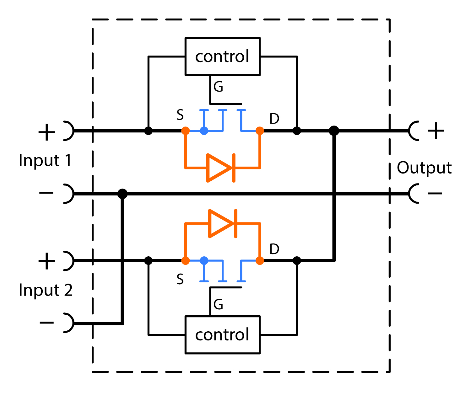 Figure 2: PULS’s new circuit design uses minimal residual voltage to actuate the MOSFETs
The circuit can be bypassed even in other critical situations, such as when the power supplies are connected to an existing short-circuit or if the input voltage has been reverse-poled.
Diodes in standard redundancy modules cause a voltage drop of 500mV between the input and output. The MOSFET redundancy modules improve this drastically. For example, in a typical new redundancy module, the PULS YR80.241, the voltage drop at 40A output current is lower than 50mV between the input and output.
Uniform power distribution
After implementing a MOSFET design, even the parallel-use mode achieves better thermal balance, improving reliability and leading to an extended lifetime. In this process, the load current is divided equally between the individual power supplies.
The parallel function can be integrated directly into the power supplies or into a standalone redundancy module. When integrated into the power supply, the output voltage is regulated so that it is around 4% higher at no-load than it is at nominal load. This results in an automatic current distribution between devices, as long as their no-load voltage is identical. If a power supply takes up more current, its voltage decreases automatically and a current symmetry is restored. This ensures that there are no power losses in the current distribution. When the parallel function is integrated into a redundancy module, the MOSFETs are used in linear mode. They generate a well-dosed voltage drop in the channel with the higher voltage so that a current symmetry is achieved between the two channels, i.e. the power supplies. This method also enables power supplies without integrated parallel-use mode to be used in parallel.
It is crucial for the parallel-use mode to always support the safety, availability and efficiency of the redundant system, both for classic 1+1 redundancy systems and for N+1 system.
Replacement without interruption
The critical connections of the YR40.245 module have plug connectors with short-circuit protection ensuring it can be replaced without voltage interruptions. Redundancy is restored immediately after replacement. This is indispensable for critical systems, when even a temporary failure could mean significant security risks or serious economic losses.