


This article originally appeared in the Dec’22 magazine issue of Electronic Specifier Design – see ES’s Magazine Archives for more featured publications.
The problem in many instances is that legacy equipment was either not designed to be connected or may use any of a number of a variety of communications protocols, making it expensive to replace them all. To ensure maximum effectiveness and obtain actionable machine data, it’s simpler and more cost-effective in many instances to implement an overlay network connecting existing automation islands and legacy equipment.
Designing such an overlay network is challenging. It requires a controller that can receive signals from sensors and other devices that use multiple communications protocols, combine those signals into a unified stream of useable data, and export that data to Edge computing resources or the Cloud. The system needs adapters that can connect directly to sensors, indicators, and other devices. Converters are needed to connect previously incompatible device types, including legacy equipment.
In addition, to ensure reliable operation, filters are required to protect data communications from electrical noise and transients. All of these components should meet IP65, IP67, and IP68 environmental standards for operation in industrial settings, and the solution needs to be easy and cost-effective to implement.
Connecting legacy equipment to the IIoT
Many factories predate the appearance of the IIoT and Industry 4.0, and it’s often not possible to interconnect all of the equipment and machines into a single network, resulting in islands of automation. Even if not isolated on an ‘island’, legacy equipment can be difficult to interconnect because of inflexibility arising from the use of proprietary communication protocols, non-standard connectors and cabling, and other factors.
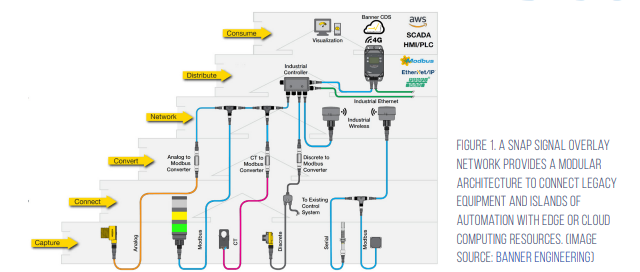
A Snap Signal IIoT overlay network can provide a quick, flexible, and cost-effective way to connect legacy equipment and islands of automation by capturing and converting various non-compatible data communications protocols into an easy to distribute standard, able to be delivered to Edge or Cloud compute resources (Figure 1).
There are several key components needed to deploy flexible and reliable IIoT overlay networks:
- Adapters to reroute wiring and link various equipment wiring schemes from sensors, indicators, and other devices to a standard overlay network format
- Data converters to translate incompatible formats found on legacy equipment or automation islands into standard protocols (e.g., IO-Link or Modbus) to enable centralised performance monitoring
- Filters to protect the data from corruption in electrically noisy industrial environments
- A programmable controller to consolidate data from multiple sources and provide local data processing and connectivity, enabling legacy equipment and islands of automation to be integrated into the IIoT
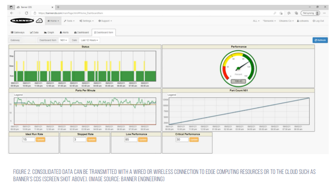
- A wired or wireless connection to distribute the collected data to Edge computing resources and/or the Cloud such as Banner’s Cloud Data Service (CDS), providing data visualisation and insights into machine performance and to send email or text alerts to support machine operation, maintenance, and repairs in real time (Figure 2).
Controller for consolidating multiple data streams
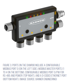
The programmable controller and data converters are key elements in designing an overlay network. Banner’s DXMR90 industrial controller serves as the central communications hub, combining signals from multiple Modbus ports into a unified data stream that is forwarded using industrial Ethernet protocols. For example, the model DXMR90-X1 includes four Modbus masters and supports concurrent communication with up to four serial networks (Figure 3).
The DXMR90 is a highly integrated communications controller that features:
- The ability to work with a range of Modbus devices, converting Modbus RTU to Modbus TCP/IP, Ethernet I/P, or Profinet
- Four independent Modbus master ports that can connect slave devices without manually assigning an address
- Local control and connectivity with: – Modbus/TCP, Modbus RTU, Ethernet/IP, and Profinet, automation protocols – Internet protocols including RESTful API and MQTT with web services from AWS, and others – Direct email alerts
- Internal logic controller (programmable using MicroPython or ScriptBasic ) with pre-defined action rules
- IP65, IP67, and IP68 rated housing
- Quick status indications with user-pro[1]grammable LEDs
- Wired Ethernet cable or a cellular enabled DXM controller used for connection to databases such as Banner’s CDS
Converters connect devices in IIoT networks
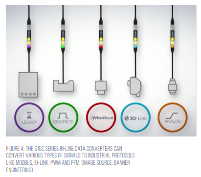
Efficient data conversion is needed to blend legacy equipment and islands of automation into an overlay network. For this function, designers can use Banner’s plug-on S15C series in-line converters to convert condition monitoring and process-sensor data from a variety of formats into digital IO-Link data (Figure 4). For example, the S15C-MGN-KQ is a Modbus master to IO-Link device converter that is user configurable to read up to 60 registers and write up to 15, with predefined Modbus registers automatically sent over IO-Link.
The S15C line of converters includes eight models:
- Six Modbus to IO-Link converters for use with Banner’s line of Modbus sensors, including ultrasonic, measuring light curtain, temperature/humidity, vibration/temperature, and GPS. Plus, a generic converter that can be configured to enable most Modbus devices to be deployed as IO-Link devices is available
- Two analogue sensor models that convert 0 to 10 volts DC or 4 to 20 milliampere (mA) signals to their digital values and forward them as IO-Link data
Wiring adapters and filters complete the network
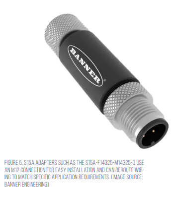
In addition to a controller and data converters, designers need wiring adapters and noise filters to quickly deploy flexible and cost-effective overlay networks. In-line wiring adapters, such as Banner’s S15A-F14325-M14325-Q, connect directly to a sensor, indicator, or other device to redirect wiring and isolate signals to match specific application needs (Figure 5).
S15F in-line filters like the S15F-L-4000-Q are also important overlay network elements (Figure 6). They can easily solve challenges with electrical noise and transient voltages that can negatively affect network performance. Installation of an S15F in-line filter can result in improved signal integrity and less need for network troubleshooting.
Snap Signal network design and deployment
The design and deployment of a Snap Signal overlay network begins with the identification of the data sources to be monitored. It then needs to be determined if any new sensors or indicators should be added to supplement existing devices.
Steps in the design of a Snap Signal network include:
- Using Banner’s system diagram approach to identify and select the Snap Signal components needed for a specific installation
- Plan the optimal wiring path, including the placement of T-connectors and filters between the devices to be monitored and the DXMR90 controller
- Determine if the installation will require the use of a wired Ethernet connection for local data consumption or the use of an Edge gateway device to wirelessly connect to a Cloud platform
Snap Signal is a true overlay network and does not require the replacement of any existing hardware.
The modular plug-and-play Snap Signal architecture makes installation easy:
- Install any new sensors or other devices and add splitter cables to every device to be monitored to maintain the existing connection with machine controls, while also providing a second path onto the overlay network
- Install the appropriate in-line signal converters
- Add T-connectors, filters and other network wiring as needed to complete the network and connect to the DXMR90 controller
- Program the DXMR90 to create custom sensing and control sequences using ScriptBasic or MicroPython programming and/or the embedded action rules
- Connect the DXMR90 to Edge computing resources using the Ethernet connection, or for Cloud connections, a cellular enabled DXM controller
Conclusion
Overlay IIoT networks can support designer needs to connect legacy equipment and islands of automation into industrial networks enabling the collection of actionable data to support increased productivity across existing factories. The design and implementation of such an overlay network is complex, but it can be greatly simplified using Banner Engineering’s topology and Snap Signal line.