


Rotary encoders are electromechanical transducers that convert angular displacement into corresponding electrical signals interpretable by digital systems. This article specifically focuses on panel mount rotary encoders—devices commonly integrated into front panels for user input applications. We’ll examine their operating principles, key performance specifications, and relevant design considerations.
Panel mount encoders – the basics
Panel mount rotary encoders are designed for installation through a panel or enclosure, enabling user-interactive control of electronic systems. These encoders generate a series of electrical pulses as the shaft is rotated, which are interpreted by a microcontroller or digital signal processor to determine angular position, direction of rotation, count, or speed.
A familiar application is the rotary control knob on consumer electronics such as audio systems. In these scenarios, panel mount encoders serve as human-machine interface (HMI) elements, facilitating real-time adjustment of system parameters.
Panel mount encoders versus potentiometers
While potentiometers also convert rotational motion into an electrical output, panel mount encoders offer distinct advantages. Encoders typically feature digital output signals, such as quadrature pulses, making them inherently compatible with microcontrollers and other digital processing units. This eliminates the need for analog-to-digital conversion, simplifying system architecture and minimising latency and quantization errors.
Additionally, panel mount encoders are manufactured to tighter mechanical and electrical tolerances than most potentiometers. This results in enhanced repeatability, improved signal integrity, and longer operational life, especially in high-cycle or high-precision applications.
Important specs and considerations
When evaluating panel mount rotary encoders for a design, several electrical and mechanical parameters must be considered to ensure proper system integration and user performance.
Resolution: PPR versus CPR: one of the most critical specifications is PPR (Pulses Per Revolution). This defines the number of electrical pulses generated per full 360° shaft rotation. Each pulse corresponds to a single low-to-high logic transition on a single channel of the encoder’s quadrature output. Alternatively, some manufacturers specify CPR (Counts Per Revolution), which refers to the number of quadrature state changes per revolution. CPR is simply PPR multiplied by 4.

Detents: are discrete mechanical stops that provide tactile feedback as the shaft is rotated. They are specified in terms of the number of mechanical ‘clicks’ per revolution and are particularly useful in human interface applications where tactile assurance is necessary. For example, an encoder with 24 detents will exhibit one click every 15°, aiding in precise manual adjustments while helping prevent unintentional rotation.
Integrated push-button switch: many panel mount encoders incorporate a SPST (single-pole, single-throw) switch activated by axial depression of the shaft. This push-to-select function is frequently used in menu-driven interfaces to toggle between parameter selection and value adjustment, enabling multi-functionality without increasing the component count.
Additional considerations
Panel mount rotary encoders typically generate two square wave signals—Channel A and Channel B—that are electrically phase-shifted by 90 degrees. This phase relationship enables directional sensing: by monitoring which signal leads the other, a microcontroller or decoder can determine the shaft’s direction of rotation (clockwise or counterclockwise).

To achieve higher resolution from incremental rotary encoders, many systems implement quadrature decoding, which tracks every logical state change of both output channels. In this method, one full quadrature cycle is defined as a complete sequence of transitions from low to high and back to low on both Channel A and Channel B. This results in four counts per physical cycle, significantly enhancing angular resolution without increasing the encoder’s physical PPR.
This technique allows engineers to extract maximum positional detail from each mechanical revolution, enabling finer control in applications such as precision instrumentation, motor control, and user-interface input devices.

Panel mount encoders also commonly utilise open collector outputs, a configuration in which the output transistor’s collector is left unconnected internally and must be externally pulled up to the supply voltage. In this setup:
- The microcontroller sources current by tying the output pin to V+ through a pull-up resistor.
- The encoder sinks current by pulling the output to ground when active.
- This forms a complete and controlled electrical path, enabling reliable digital communication between the encoder and host controller.
The open collector topology offers electrical isolation, noise immunity, and flexibility in interfacing with logic families operating at different voltage levels.
Lastly, it is important to note that microcontrollers use different methods for counting:
- Pulses on one channel:
- 1 count per rising (or falling) edge on one channel
- Suitable for low-resolution applications
- Pulses on two channels:
- Counts both rising and falling edges on both channels
- 2 counts per cycle
- Provides a moderate increase in resolution
- Quadrature state changes:
- Detects all four logic state transitions per cycle (00, 01, 11, 10)
- 4 counts per cycle
- Maximises resolution and directional fidelity
Comparing encoder technologies
Panel mount rotary encoders primarily operate based on two core sensing technologies: mechanical and optical. Each approach comes with its own tradeoffs in terms of cost, signal integrity, durability, and resolution, influencing suitability for different application environments.
Mechanical rotary encoders function as a series of contact-based switches. The code wheel is outfitted with conductive segments or pads spaced evenly along its perimeter. A fixed contact, mounted on the encoder housing, intermittently connects with these segments as the shaft rotates. Each make-or-break event of the circuit generates a voltage pulse, forming a square-wave output that can be interpreted by digital systems.

Due to the inherent nature of mechanical contacts, switch bounce occurs as contacts momentarily chatter between high and low states during transitions. This results in signal noise, which can be misinterpreted by microcontrollers as additional unintended pulses.
To suppress this undesired behaviour, debounce circuitry is implemented to filter out short-duration transitions and produce a stable digital output. This circuitry typically leverages either hardware or firmware to restore signal integrity. Ensuring clean, deterministic output from mechanical encoders is vital, especially in applications demanding precise incremental position tracking or user interface consistency.

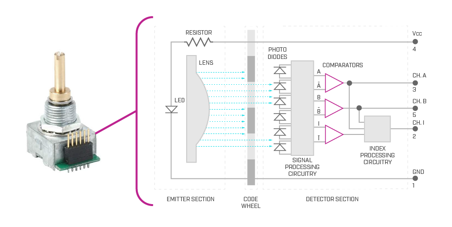
Optical encoders utilise non-contact sensing to achieve superior precision and signal cleanliness. These encoders consist of three fundamental components:
- Light source (typically an infrared LED)
- Photodetector
- Code wheel with evenly spaced slits
As the code wheel rotates, slits alternately allow or block the light beam. The photodetector converts these interruptions into square wave signals, corresponding to shaft movement.
Unlike mechanical encoders, optical encoders require no debounce circuitry due to their contactless nature and fast, clean signal transitions. They are well-suited for high-resolution applications such as precision instrumentation, robotics, and motor feedback.
To summarise this comparison, mechanical encoders are cost-effective, support wide voltage ranges, and are well suited for basic user interfaces. However, they require debounce circuitry to eliminate signal noise and have a shorter lifespan due to contact wear. Optical encoders, though more expensive, offer higher resolution, cleaner signals without debouncing, and a longer operational life, making them ideal for precision and high-duty-cycle applications.
Summary
Panel mount encoders remain a critical component in human-machine interfaces across numerous industries. Selecting the right encoder demands a solid understanding of underlying technologies, key performance specifications, and integration requirements.