


According to some in the industrial sector, including the German government, we are on the verge of a fourth industrial revolution. Just to recap, the first industrial revolution was triggered by water power and the invention of the steam engine, which mechanised many previously manual tasks. Electrical power and mass production brought about the second industrial revolution, while the third, the digital revolution introduced electronics and computer automation to factories. The fourth industrial revolution promises to enable smart factories, capable of optimising and reconfiguring themselves, using data about the machines’ environment fed in by sensors. Driven by competition within the industry, communications and control technologies are developing further to bring the vision of Industry 4.0 closer to reality.
“Industrial companies in Europe are competing against Chinese low cost labour,” explains Chris Neil, Senior VP of the Industrial and Medical Solutions Group at Maxim Integrated. “Factories therefore need to maximise throughput and uptime, including being able to reconfigure the factory quickly when required.” The vision of Industry 4.0 is already starting to change the shape of the electronic systems within factories. Previously, factory automation relied on a large, central PLC which communicated with all the equipment on the factory floor. The communication loop was long and was therefore prone to problems. The latest generation of factories instead uses distributed control; many smaller PLCs are used instead of one large one, and they are placed closer to the tools they are controlling. This makes the factory a lot easier to reconfigure and reduces the problems caused by attempting to communicate remotely with a central hub.
These small PLCs are evolving into tiny, low power systems that can accept multiple sensor inputs and make decisions about what to do based on what the sensors are telling it. These tiny PLCs have to be high performance, while remaining small in terms of form factor and power consumption.
Micro PLC platform
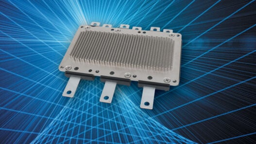
In order to show exactly what state-of-the-art electronics can do to improve the performance of industrial PLCs, Maxim has introduced the Micro PLC reference design platform. The platform is made up of several reference designs, each of which can be used as a standalone subsystem. As a demonstrator, the company has also commissioned a Micro PLC device using the reference designs as a proof of concept (see image above). The demo PLC uses between 40 and 45 Maxim components; the idea is to show off the cumulative effect of minor advances in performance brought by the individual components. This demo system was shown at electronica 2014 at Maxim’s Beer Mug Factory, where it was used to drive an assembly line controlling a sophisticated robot and sensor array (Figure 1). The Beer Mug Factory allowed visitors to the stand to customise a beer mug with their signature, as well as detect which beer the visitor would like by detecting a coloured token placed in the mug.

Figure 1 – Maxim’s electronica booth featured a Beer Mug assembly line controlled by the Micro PLC demonstrator
The demo PLC system is based on several Maxim Micro PLC reference design subsystems to form an IO link, RGB sensor, weigh scale, light curtain and temperature sensor. The first thing to notice about the Micro PLC demo is that it’s just 57mm tall. Maxim is claiming the title of ‘world’s smallest PLC’, saying the device is overall ten times smaller than competitor products. Possibly the most impressive claim Maxim is making about the demo PLC is that its digital I/O operates at a massive 70 times faster than competing systems. This is down to Maxim’s soon-to-be-launched MAX14900 quad-channel 24V digital interface, about which details are unfortunately quite scarce right now. Maxim will also launch two brand new digital I/O reference designs, MAXREFDES63# and MAXREFDES64#, which describe digital output and digital input subsystems, respectively.
Both the digital input and output reference designs will also feature the MAX17515 step-down converter module. This switch-mode power supply includes dual n-channel MOSFET power switches, a fully shielded inductor, as well as compensation components. It operates at a fixed frequency of 1MHz to reduce input and output capacitor size. The device supports 0.75 to 3.6V programmable output voltage and 5A output current.
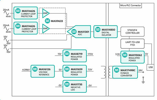
Figure 2 – A block diagram of the MAXREFDES61# reference design for a quad analogue input
The analogue I/O for the demo system is also top spec, with the weigh scale and temperature sensor’s quad analogue inputs both based on the MAXREFDES61# reference design. Two of the input channels accept -10 to +10V signals and the other two inputs accept 4 to 20mA signals. The reference design uses 11 Maxim parts plus an STM32F4 MCU from STMicroelectronics (see block diagram in Figure 2). A high efficiency DC/DC converter, the MAX15062, helps keep power consumption below 500mW and the entire system fits into an area the size of a credit card.
The weigh scale’s analogue output subsystem is based on the MAXREFDES60# reference design, which produces a precise 16-bit analogue output with error less than 0.05% over the entire range (shown in Figure 3). Like the analogue input subsystem, it incorporates an STM32F4 MCU, DAC, power supply, voltage reference and digital isolator. The analogue output reference design also uses the very efficient, isolated MAX17522 step-down converter to help keep power consumption down to 240mW.

Figure 3 – The MAXREFDES60# reference design for a quad analogue output
The digital isolator used for Maxim’s electronica demonstrator is the recently introduced MAX14930 (not the MAX14850 from the reference design). This device is three times faster than the competition, while providing 2.75kV of isolation for interfaces to low voltage (1.8V) devices. Devices are available with data rates from DC up to 1, 25 or 150Mb/s.
Protection and power
As well as I/O, Maxim’s demo system also claims several other performance improvements. The over-voltage and over-current protection device used to detect short and open circuits is 30% smaller than the competition and uses no external components. The MAX14588 protects systems against voltage faults up to ±40V; its range is adjustable between 6 and 36V. The undervoltage range is adjustable between 4.5 and 24V. The MAX14588 also features programmable current-limit protection up to 1A; it can be set for auto-retry, latch-off or continuous fault response when an overcurrent event occurs.
The demo system is also said to run 50% cooler than competing systems, helping reduce the need for a fan. Fans are noisy, they can spread dust and contamination in industrial environments and they are often the least reliable part of any electronic system. They are also bulky, wasting space. Reducing the heat lost by the power systems is therefore very desirable if it can eliminate the fan altogether.
Ultimately, the PLC is a key part of Industry 4.0. The addition of intelligence to factory equipment, combined with distributed control, will result in faster throughput and greater uptime, reducing the costs of production. Maxim’s reference design platform is an indicator of how advances in integration and power saving are driving smaller, faster and more efficient PLCs, which will eventually enable the industry of the future.