


Filters will give their full quoted performance up to their full rated current. For instance, 30A filters will give full performance where used at a lower, 20A, current. The chief exception is for single-line filter designs where the magnetic core will progressively saturate and give lower inductance and lower performance as load current increases. A reputable filter manufacturer should allow for this and quote performance figures based on the worst case, full load condition.
It is not a good idea to use a 10A filter continuously at 12A, so that it is 20% over-rated. The heat dissipation within a filter is proportional to I2. Therefore a 20% overcurrent will represent 44% excess heat dissipation, which is unacceptable. Filters should never be used at above their rated current on a continuous basis.
You can use a 240V 50Hz mains filter on 120V 50Hz. Filters are normally suitable for operation at any voltage up to their rated voltage provided that their current rating is not exceeded, and the supply frequency is no greater than the rated frequency. It is also normally possible to use AC filters on DC supplies up to at least the same working voltage. Where filters are fitted with transient suppressors, it should be remembered that the level of transient suppression provided may no longer be optimum for the new working voltage.
It is sometimes possible to use a 240V 50Hz filter on a 115V 400Hz supply, especially when the filter capacitance values are low. The main problem lies in the heating effects of 400Hz supplies on the inductor cores and capacitors within the filter. In the case of the filter capacitors, leakage currents will be about four times higher on the 400Hz supply. Capacitor heating by the 400Hz supply can be significant on high-performance filters. This can be reduced by using low-loss capacitors in the filter design, but careful consideration needs to be given to harmonics on the 400Hz supply which will add to heating effects. The filter current rating may also have to be derated to take account of the additional heating within the inductor cores. Always contact the filter manufacturer for advice before proceeding.
Concerning filters used on higher frequency supplies and non-sinusoidal supplies, a check must always be made to ascertain the likely heating effect of a particular supply on any given filter. The heating effect will increase with frequency and will be even more pronounced for non-sinusoidal waveforms because of the high harmonic content. The filter manufacturer should be consulted for advice, as it is unlikely that a standard filter will be suitable, although a special design may well be practical.
You cannot generally utilise a powerline EMI filter for filtering out mains harmonics. Mains harmonics are most pronounced at the lower frequencies and have a very low source impedance. They will require very large values of capacitance and inductance to filter them out, and a purpose-designed harmonic filter is required to do this. A high-performance mains EMI filter will reduce some of the higher order harmonics which extend into its stop band, but its impedance is unlikely to be low enough and its capacitance and inductance values will not be high enough to have any great effect on the lower order harmonics.
If a high-performance powerline filter is placed on a supply known to contain high levels of harmonics, say >5% THD, care must be taken to choose a filter which will not be overheated by the harmonics, in the same way that the harmonics will cause overheating in transformers, cables and other electrical equipment on the same supply. The filter manufacturer must be contacted for advice on this matter.
A filter containing feedthrough capacitors may still be needed where you do not require any significant suppression performance above 10MHz. Because of their construction, feedthrough capacitors have lower series resistance and inductance in their connections than two terminal capacitors. They can therefore offer better performance in circumstances where these parameters are important, such as where capacitance values need to be large.
Where pre-compliance testing shows the need for a filter with an attenuation of 30dB at 50kHz to remove noise peaks, a catalogue filter claiming 40dB insertion loss at 50kHz may not work when connected into the circuit. This is most likely because the source impedance of the noise is not 50 ohms, yet the filter chosen has its insertion loss specified in a 50-ohm system. A filter is needed which will provide the required attenuation in the impedance of the practical system. Alternatively, the filter picked may only provide attenuation in the asymmetric mode whereas the noise could be in the symmetric mode, or vice versa. The application should be discussed in detail with the filter manufacturer who can give guidance on the performance of appropriate filters in systems other than 50 ohms and for both modes of interference.
For good filter performance above 10MHz, it is advisable to mount the filter through or against a bulkhead to avoid bypass coupling between incoming and outgoing leads. The effect gets worse as frequency increases, so that mounting on a bulkhead or, alternatively, using screened leads becomes increasingly important. Many simple filters not containing feedthrough capacitors will have gone into resonance by this frequency anyway, so there would be little benefit to be gained by bulkhead mounting. However, for high-performance filters employing feedthrough capacitors, a very significant benefit will be obtained at the higher frequencies.
In conclusion, because of a greater awareness, EMC considerations are taken into account in equipment design to a much greater degree than they used to be.
However, the selection of a filter from any catalogue without being aware of its full specification under practical circuit conditions may still not yield the expected results. This is usually because the parameters of the circuit to be suppressed are not adequately defined, or not known. Probably the least well understood parameters are the source and load impedance of any interference, but there are many other parameters which can cause problems if not taken into account.
A reputable filter manufacturer should always be prepared to give impartial advice on the best choice of filter for a given application. Where a filter manufacturer is able to offer a bespoke design, it is often found that a custom-designed filter can offer a more cost-effective approach than a standard catalogue item, even in cost-conscious commercial environments. This is because, as well as precisely meeting the electrical requirement, it can also offer simplified installation by virtue of its tailored mechanical design.
Examples of standard catalogue filters designed to address specific practical application considerations:
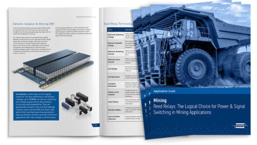
1. Catalogue filters for Switched Mode Power Supply (SMPS) applications
##IMAGE_2_C##
These have been designed to incorporate all of the special requirements imposed by SMPS circuits which require filtering. i.e. feedthrough capacitors, suitable for low source impedance, good asymmetric and symmetric performance, bulkhead mounting.
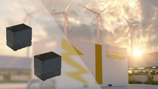
2. Catalogue filters for Military Vehicles
##IMAGE_3_C##
Many items of equipment in military vehicles such as blower or wiper motors need filtering at frequencies beyond 1GHz, and it is not always practical to fit filters though a bulkhead or mount equipment inside a shielded enclosure. A standard solution is to use a filter with integral screened cables which shield the “dirty” cables emerging from the equipment, to prevent the cables radiating until the noise has been safely removed by the filter.