


This methodology enables to provide working prototypes to customers in a very short time, reacting fast to their requests. Moreover, it increases the level of confidence to the design, before a test chip or the final silicon is available – a great benefit for concept, design and verification engineers.
In particular, product models, developed during concept and feasibility studies in SystemC, are translated automatically into HDL ready to be synthesised into FPGAs for prototyping by the customer. The generated HDL is first automatically validated via co-simulations with SystemC, then the FPGA prototype is tested in a laboratory system test bench and finally the measured results are again automatically compared to simulation results. The flow is highly automatised and allows time and effort to be saved when developing a prototype, without compromising on performance and reliability.
Electrification and autonomous driving are changing requirements in the automotive world. Even in standard applications like engine, transmission and wheel speed sensors the room for innovation is big. OEMs and Tier1s want to try new algorithms, architecture and sensor technologies in the field, and therefore ask for hardware prototypes. The hardware prototypes are normally developed within months and are characterised by dynamic changes of requirements to find the perfect fit with the application.
The standard project-driven approach, where people with different backgrounds (concept, application, analog, digital design, verification, etc.) work on the project for a number of years cannot longer be used. For this reason, Infineon developed a methodology was developed that allows a smooth transition from the idea to the real hardware prototype. The vision was to enable concept and applications engineers to develop a hardware prototype without a big effort and the need of a complete team. Starting from a model, which is verified extensively via simulations, Hardware Description Language (HDL) is generated with a High-Level Synthesis (HLS) tool and co-simulated with the golden reference SystemC model. When the simulation shows a pass, the code is synthesised onto the real FPGA (Field Programmable Gate Array) hardware and tested in the laboratory and in the field.
The goal was to develop a complete methodology allowing the transition from concept to implementation in a fast, flexible and lean way. Once a product model is available in SystemC / SystemC AMS (this is normally developed during concept phase), the translation to HDL is performed automatically and the virtual prototype becomes a real prototype that can be delivered to customers and even tested in the application.
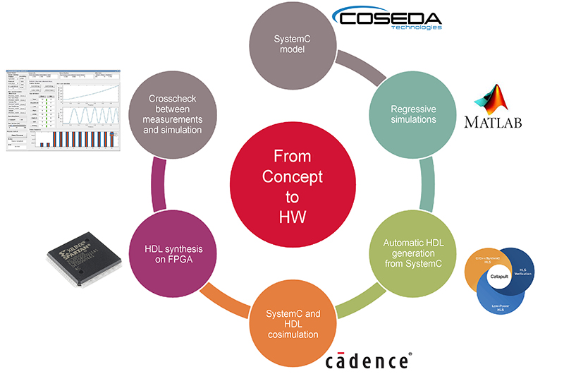
The methodology flow can be summarised in the following main points: idea, verification of the idea, from idea to implementation, verification of the implementation, from implementation to real hardware and verification of the real hardware.
The sensor model development was done in SystemC. Sensing element, analog path and digital core are modelled in SystemC and SystemC AMS, followed by validation of the model via regressive simulations. Thousands of simulations are run iteratively, covering various use cases with real world inputs. The next step is automatic translation of the code to HDL, ready to be synthesised on FPGA. Effort to write VHDL or Verilog code is saved, performing an automatic translation of the digital core from SystemC to HDL.
Automatic co-simulation of HDL and SystemC is done, reusing the test setups written to verify the model. The same stimuli generator and evaluator used to verify the SystemC are used to simulate the HDL as well. Given the same inputs, the outputs of the SystemC and HDL should match. Than the synthesis on FPGA follow with automatic comparison between measurements and simulation results. For selected use cases it is possible to provide the hardware and the model with the same input stimuli. Given the same input stimuli, the outputs of the SystemC model and of the real hardware should match.
Sensor model development in SystemC
The methodology described here has been applied on a magnetic speed sensor to be used in automotive transmission application. Magnetic speed sensors sense the speed and rotational direction of a rotating wheel and are used in various applications (wheel speed, transmission, crankshaft and camshaft) because they provide a contactless, robust and low-cost solution. Typically, a magnetic encoder is applied to the shaft and the sensor senses the magnetic field variation generated by the rotation. Alternatively, a back-bias magnet can be used to generate a constant field that is modulated by the rotation of a steel wheel. The two options are shown below.
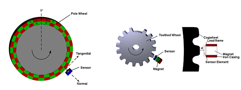
To sense the magnetic field, different sensing element types are used. The most common are the Hall principle or via the measurement of a resistor which varies with magnetic field such as GMR (Giant Magneto-Resistance), TMR (Tunnel Magneto-Resistance) or AMR (Anisotropic Magneto-Resistance).
Product models based on SystemC are widely used to simulate the behaviour of an integrated circuit to reliably assess the clarity and completeness of the requirements definition, explore different possible architectures and verify the hardware requirements of each block.
Taking the internal block diagram and product requirements as a reference, a SystemC model of the next generation transmission sensor has been developed. In particular, to describe the analog modules SystemC AMS has been used, while for the digital domain plain SystemC has been chosen.
For correctly describe the behaviour of the sensors a detailed description of the digital algorithms is needed and SystemC allows to describe digital behaviour very well. Moreover, simulations are faster and easier to run compared than to hardware description languages like Verilog or VHDL and can be executed both on Windows or Unix. Lastly, once compiled, it is possible to share the model with customers protecting the intellectual property.
Simulation and validation of the model via regressive simulations
The SystemC model is validated against real world use cases with thousands of simulations. The simulation flow is described below.
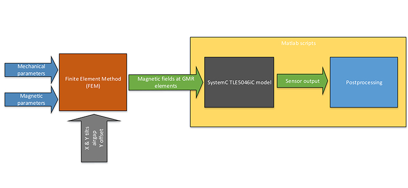
Finite Element Method (FEM) simulations are used to obtain the magnetic field vector that is used as an input for the SystemC model. In this work, the flow has been improved increasing the number of use cases and the level of automation. In particular, the stimuli generation and output evaluation take place now in SystemC, increasing the speed of the simulations. Matlab scripts control the model parameter and test case configuration.
The stimuli generator, is capable of generating the following use cases, taking the magnetic field from FEM simulations as an input: Forward / Backward rotation, change of direction, sudden airgap change, angular and airgap vibrations, wheel run-out and stray field influence.
Automatic translation of the code to HDL
The SystemC code of the digital core has been written taking into account the need for a VHDL translation. From this perspective, all the language constructs which are possible in SystemC, but not synthesisable have been avoided, as well as the use of “double” data types and complex C++ structures.
Mentor Catapult software has been used to translate each SystemC module of the digital core into VHDL. The result was a set of VHDL modules, with the same hierarchy as the SystemC modules.
In total, around fifteen SystemC modules have been converted, each of them with a complexity of around five hundred lines of code. An expert digital designer would have taken months to convert the behaviour of the SystemC model into an HDL to be synthesised on the FPGA. With Mentor Catapult the translation process was performed in just around a day. The high-level synthesis approach can save various man-months of effort. This is a crucial point for prototyping activities, where speed is essential.
Automatic Co-simulation of HDL and SystemC
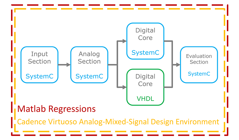
To verify the translation, Cadence Virtuoso environment was used to co-simulate the VHDL translation of the digital core and the SystemC model. In Virtuoso, a schematic was realised in which the SystemC “Input section” module was instantiated. The analog part of the sensor was wrapped in an “Analog section” SystemC module and fed with the signals coming from the input section. The same was done with the ADC SystemC module. The outputs of both the analog section and the ADC were connected to the SystemC digital core module and to the VHDL translation of the same. The outputs of the two digital core implementations (VHDL and SystemC) were connected to two analog interface SystemC modules. Two “Evaluation section” SystemC modules were instantiated to evaluate the outputs of the two analog interface modules. A simplified structure is shown below.
 This work flow enabled the co-simulation of the SystemC and VHDL code of the digital core, by using the same inputs and the same evaluation logic for both. The result of the co-simulation consists then in two different reports, one for VHDL and one for SystemC, characterising the output pulses of the two output signal, in order to compare them. The figure below shows an example of co-simulation.
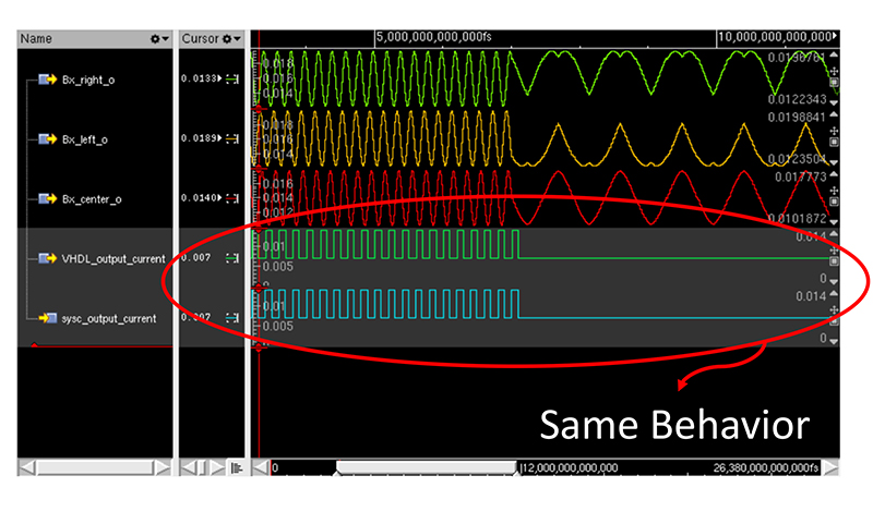 The results revealed proper behaviour of the VHDL translation, and a good match with the SystemC behaviour, except for some small timing differences due to the way High Level Synthesis is performed by the tool. With the Catapult tool a full match has been obtained.
Synthesis on FPGA
Once the HDL code has been validated in the previous step, it is possible to move the design to the real hardware. The hardware currently in use in the laboratory consists of three boards:
xMR board, Analog Front End (AFE) board and FPGA board (below).
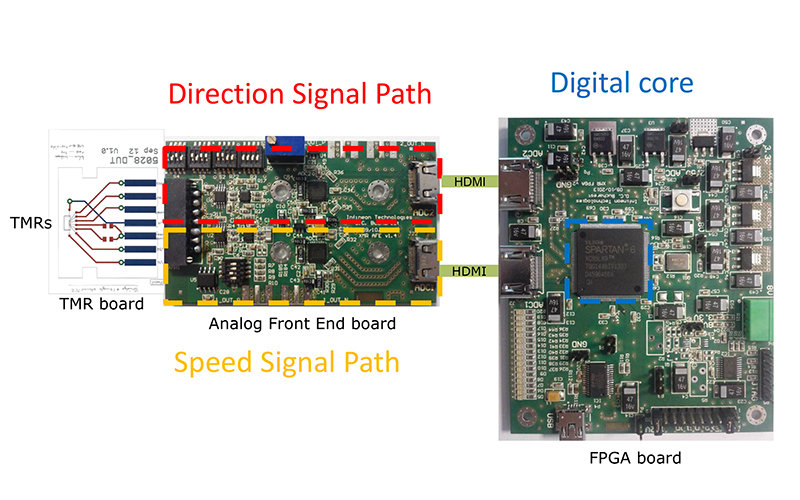
The xMR board consists of bare die silicon with of one or more sensing element (either GMR or TMR resistors) bonded on a small PCB. The PCB is then connected to the Analog Front End. The AFE board models the analog front end of a speed sensor with a cascade of amplifiers and Analog to Digital Converters (ADC). This board is partially configurable using DIP switches: both the amplifier gains and the sensing element configurations can be changed. Finally, on the FPGA board the digital core of the sensors is implemented. The board uses a Xilinx Spartan 6 FPGA and provides some input and output pins for sensor configuration and debugging.
In the future, some other options could be considered, for example: Programmable front end instead of AFE board or System on Chip (SoC) instead of simple FPGA.
Automatic comparison between measurements and simulation results
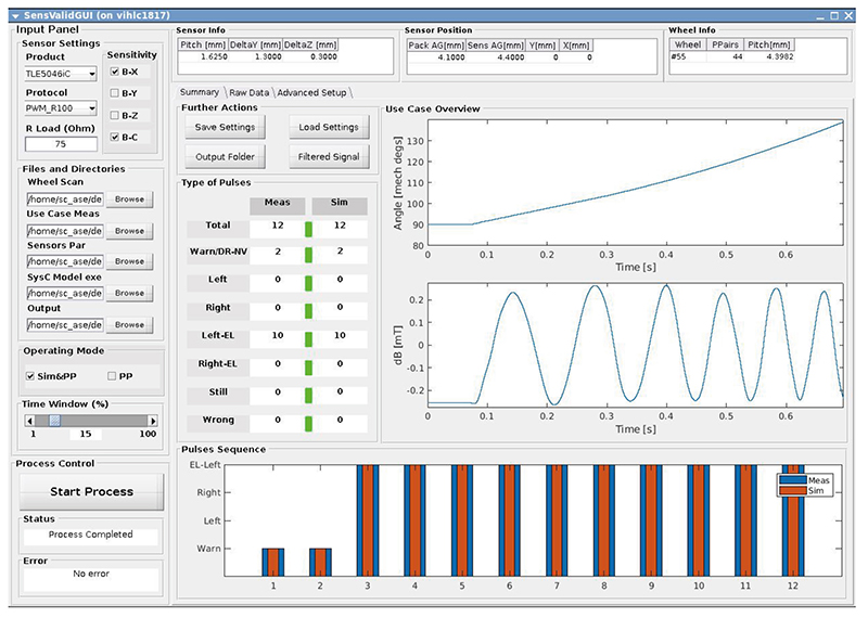
Finally, as part of the new methodology, an automated co-verification of the hardware is performed against the golden reference SystemC model. The validation methodology is described by the following workflow: Both the outputs and the stimuli of the system are measured (outputs come from the sensor while the magnetic stimuli are produced by the movement of the wheel). For the simulation, the model is provided with the stimuli previously measured on the real test bench. An algorithm performs a post processing of the data coming from both hardware and software for stimuli generation and final comparison purpose. Then, the post processed data is collected and assessed according to predefined validation criteria in order to crosscheck the hardware versus the model and find eventual mismatches to be fixed. The figure below shows the Graphical User Interface (GUI) of the co-verification environment.
Results and conclusion
The described methodology is already in place, and is currently used for all next generation transmission sensors and for some other products. For example, the combined measurements and simulation method has already been very useful to support design-in activities with new wheel-speed sensors.
The VHDL to be synthesised in the final silicon can be co-simulated with the reference SystemC model, reducing the number of bugs and the effort in verification. The prototype (and the final silicon) can be tested on laboratory test benches and the measured results can be compared with the simulations results. In conclusion that virtual and real prototyping is a very useful and powerful tool, to validate the application requirements, via simulation and actual measurements. Using the proposed methodology, going from idea to final implementation, is faster and easier than with a standard approach.