


Although their reliability benefits from the fact that they have no moving parts, there are still several factors that can degrade their performance if not properly implemented.
To aid in this understanding, this blog provides an overview of basic Peltier module construction and common factors that can impact Peltier module performance and reliability.
Basic peltier module construction
Thermoelectric coolers are solid-state devices with no moving parts. At their core, TEC modules are comprised of positive and negative doped semiconductor pellets situated between two electrically insulating but thermally conductive ceramic plates.
On the inner surface of each ceramic plate are conductive metal patterns that the semiconductor pellets are soldered to. The semiconductor pellets are then configured in such a way that makes them mechanically in parallel and electrically in series.
The series electrical connections give the desired thermal effects, while the mechanical configuration leads to heat being absorbed from the cold side ceramic and released by the hot side ceramic.
For more information on a Peltier module’s working principles and construction, CUI Devices’ technical paper provides a more in-depth resource.
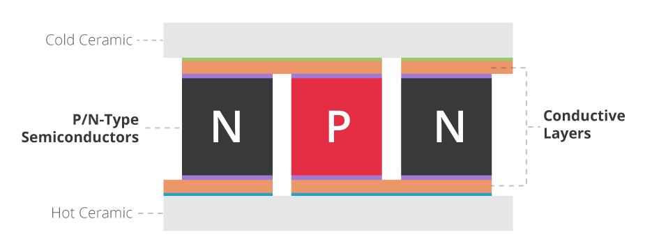
Figure 1: Basic Peltier module construction
Typical failure mechanisms
A Peltier module’s most common failure mechanism is the mechanical fracturing of the semiconductor pellets or solder joints. Thankfully, these fractures can be detected by observing a rise in the series resistance of the Peltier module, resulting in a reduction of its overall efficiency. While these fractures do not initially propagate across the entire pellet or solder joint area, they can eventually spread and cause a complete device failure.
Shear and tension stress
A common Peltier module application starts by placing the cold plate of the TEC module on an object to be cooled followed by a heat sink on the hot side to help dissipate heat.
However, large shear or tension forces can occur across the module if no mechanical structure is used to support the cooled object and heat sink. If the object and heat sink are simply attached to the ceramic plates without additional support, the Peltier module could break or fail under these forces that they are not meant to withstand.
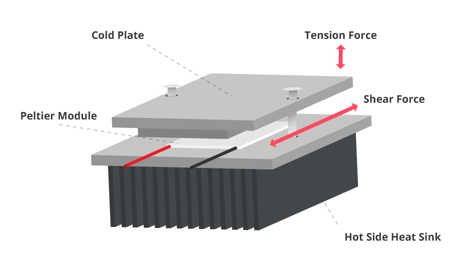
Figure 2: Shear or tension forces in a Peltier module assembly
Because of a Peltier module’s ability to withstand large compressive forces from clamps, many applications prevent tension and shear forces by clamping the Peltier module in between the object to be cooled and the heat sink. This then allows the clamps to take in any shear or tension loads generated by the object and heat sink.
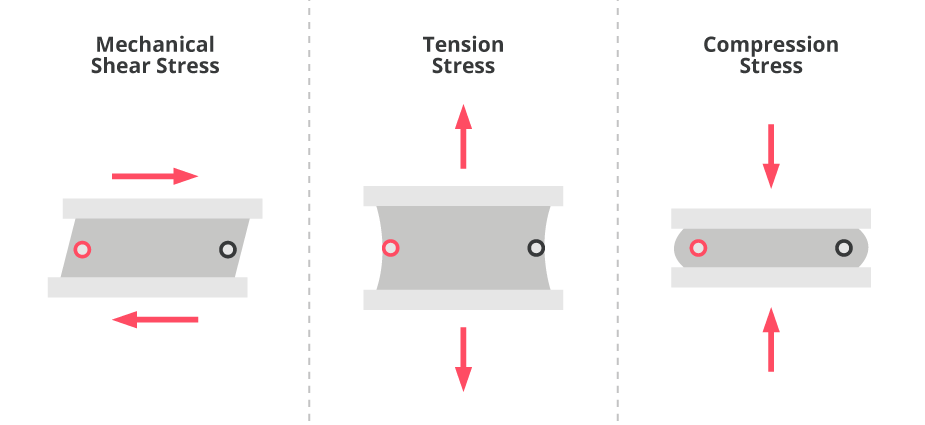
Figure 3: Typical stresses on a Peltier module
Mechanical compression forces
As mentioned above, Peltier modules can tolerate large compressive loads from clamping, but if not properly implemented, uneven clamping forces can lead to their own set of problems. These uneven clamping forces can produce torques as well as compressive forces between the ceramic plates that result in mechanical failure.
Therefore, it is crucial to apply even forces across the TEC module during clamping to minimise torque and other potentially damaging loads.
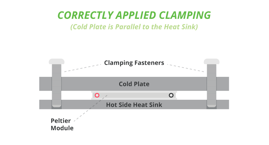
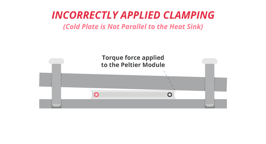
Figure 4: Correct and incorrect Peltier module clamping
Thermal cycles
Each of a Peltier module’s semiconductor pellets and ceramic plates have associated Coefficients of Thermal Expansion (CTE). During the typical cycles of heating and cooling, fractures can occur in the semiconductor pellets and solder joints due to a mismatch of the ceramic and semiconductor CTEs.
Furthermore, changes in a thermoelectric cooler’s absolute temperature, rapid rates of change in its temperature, and thermal gradients across the TEC module can cause mechanical stresses due to the CTEs. Additional areas that can lead to mechanical stress and eventually device failure include operation at extreme temperatures, large temperature gradients, and high temperature slew rates.
Contaminants
Contaminants from outside sources are another potential path to decreased reliability for a Peltier module’s semiconductor pellets, solder joints, and conduction paths. To combat external contaminants, many Peltier modules have sealant applied around the outer edges between their two ceramic plates.
Silicone rubber and epoxy are two of the most common sealant options for a Peltier module, with each having certain advantages and limitations. Silicone rubber is often chosen for its mechanical compliance but can be limited as a vapor barrier in extreme environments.
On the other hand, epoxy works well as a vapor barrier but typically lacks the mechanical compliance of silicone rubber. Which sealant a designer chooses will ultimately depend on the operating environment of the intended application.
Improved reliability in peltier modules
CUI Devices has developed the arcTEC structure as a way to counteract the mechanical stresses outlined above that can result in cracks forming in a Peltier module’s semiconductor pellets and solder joints. Found its line of high performance Peltier modules, the arcTEC structure’s unique construction combats the effects of thermal fatigue to improve reliability, cycle life, and performance. It accomplishes this task in several ways.
First, it replaces the solder joints on the cold side of the module with a more mechanically compliant, electrically conductive resin, which reduces stresses and fracturing that can occur in traditional Peltier module structures. It then replaces the rest of the solder joints with high temperature antimony solder (SbSn).
With a melting point of 235°C, antimony solder can tolerate mechanical stress better than the more commonly used bismuth solder (BiSn) and its 138°C melting point. CUI Devices’ Peltier modules also utilise a silicone rubber vapor barrier for further mechanical compliance. Epoxy and other vapor barriers are available upon request.
By plotting the resistance against the number of thermal cycles, the graph below clearly shows the improved reliability of CUI Devices’ arcTEC structure. As a noted earlier, higher changes in resistance cause a higher chance of mechanical failures. Whereas standard Peltier modules demonstrate spikes in resistance after as few as 3,000 thermal cycles, the arcTEC structure maintains stable performance beyond 30,000+ cycles.
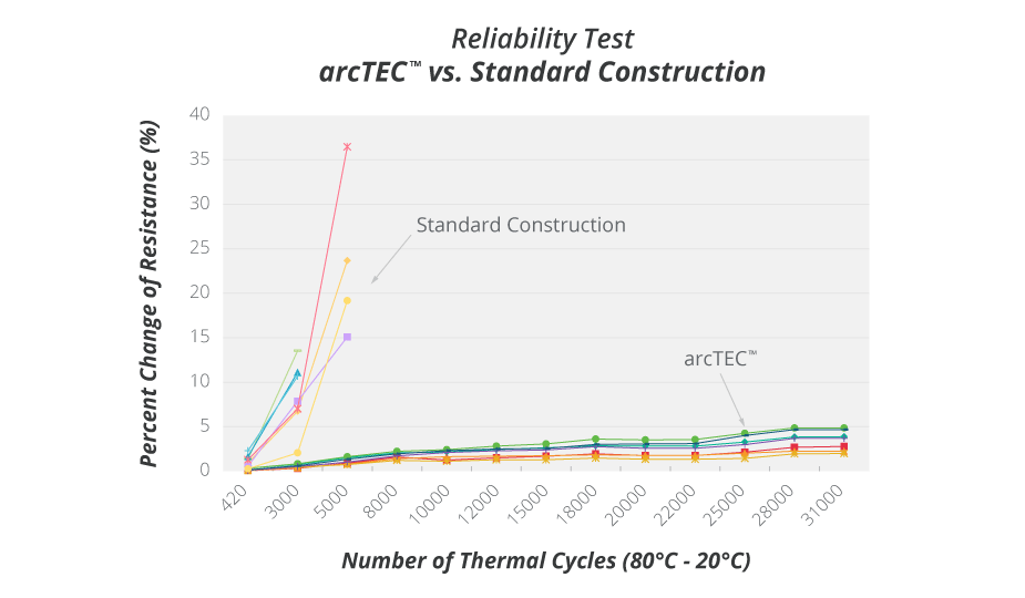
Figure 5: Graph highlighting the more stable performance of the arcTEC structure
Conclusion
As with any component, reliability is an important part of the selection process with a multitude of factors potentially impacting performance. For Peltier modules, these factors can include the operating conditions, installation, and contaminants from outside sources.
Several of these factors can be counteracted by observing proper installation techniques and operating limits. Outside of these considerations, CUI Devices’ arcTEC structure can further overcome the limitations of more traditional Peltier module structures with its unique construction and improved reliability.
Offering a variety of sizes and thermal ratings, CUI Devices’ Peltier devices allow engineers to find the right match for their thermal management challenges.