


Mechanical systems, such as power windows, have long been standard features of the modern car, but power seats and power lift gates are now making the move from optional extras to standard equipment. 60% of US vehicles already have such equipment fitted and the Chinese automotive consumer expects electric seats without recourse to any manual adjustment. As the drivetrain moves to hybrid and fully electric, and the dashboard and user interface morphs to match 21st-century visions, consumer expectations for electric-everything are growing rapidly. In turn, we are seeing rapid evolution in the technology required to implement these comfort features.
Comfort motor drive requirements
Many of the requirements to enable mass market availability of comfort features are straightforward. The physical volume of the solution and, to some degree, the weight, plays a role. System efficiency, both when active and in standby, is important, particularly for electric vehicles (EVs). In addition, there is a drive to reduce audible noise, especially in premium and electric vehicles. Electromagnetic compatibility (EMC) must be considered from the outset. Above all, robustness, reliability and safety are at centre stage.
To meet these requirements, the industry is moving away from the mechanically-based switches and relays used in early-generation motor drive applications. It is essential that all electronics components can handle both the rough mechanical and noisy electrical environment. Diagnostics are also a critical aspect, demanding that each comfort motor drive engine control unit (ECU) can be interrogated over in-vehicle networks. Finally, the fulfillment of ASIL safety requirements is necessary to ensure the safety of occupants against pinching or crushing, even under failure conditions.
Keeping pace with the increasing adoption rate, electronics suppliers are rapidly developing greater levels of chip-level integration to achieve the reduced size, increased reliability and robust feature sets needed for the next-generation of power lift technologies. The block diagram in Figure 1, applies to many of today’s power seat and power closure implementations.
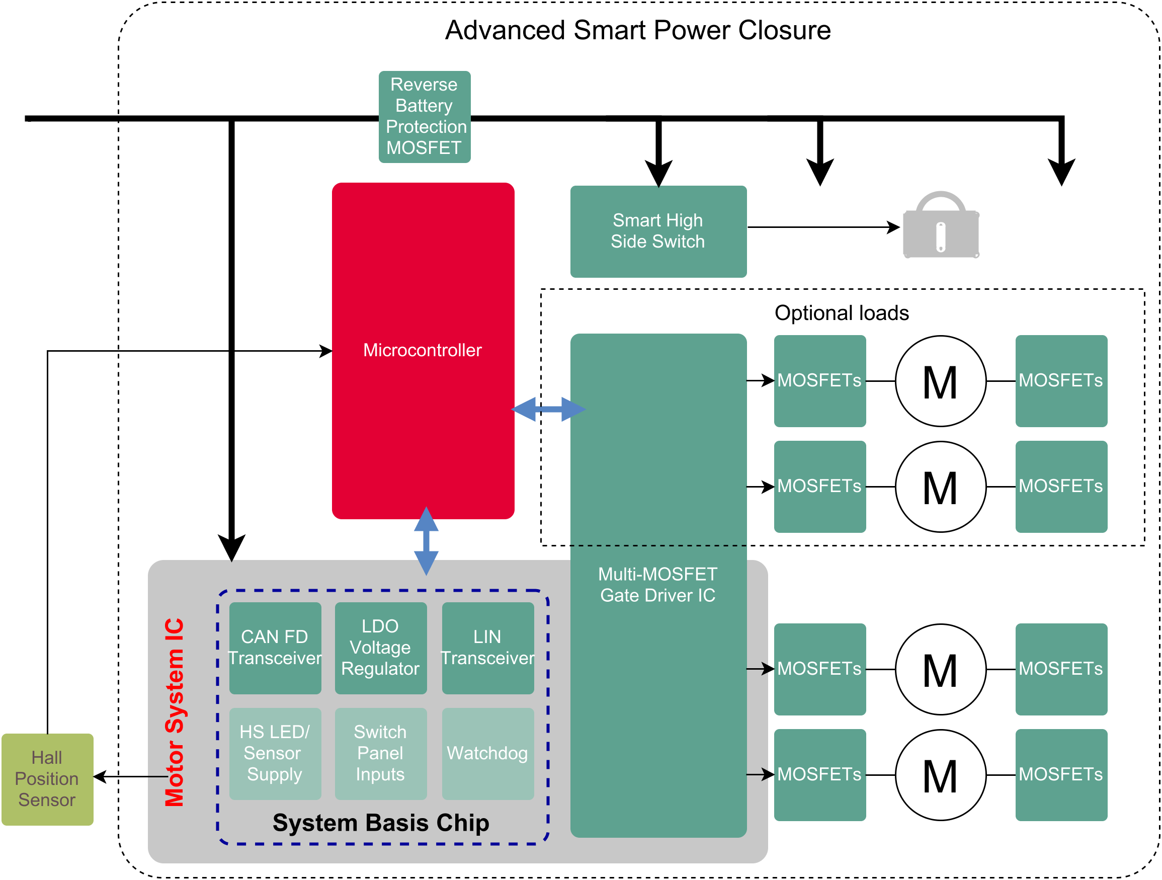
Figure 1: The advanced smart power enclosure, typical of power seat and power closure implementations in use today.
Newer system designs now benefit from simplified development and testing, improved in-vehicle diagnostics, greater system efficiency and an overall better customer experience.
Major system blocks include a microcontroller (providing control, networking and implementation of the safety concept), power conversion, as well as transceivers used for a LIN (local interconnect network) or CAN-FD (controlled area network flexible data rate). The power control block is protected by a reverse battery MOSFET. From here, gate drivers link the microcontroller with the power MOSFETs in an H-bridge configuration offering the required directional and speed control. Position sensing and localised control buttons, along with supply sensing, complete the design. It is a given that each device in the motor drive controller is AEC-100 qualified.
Increased integration
Infineon’s MOTIX motor system ICs(Figure 2)encompass these functions, except for the microcontroller and the MOSFETs, in one compact VQFN-48 7.0 x 7.0mm package. The high level of integration translates to a high design density and cost efficiency for the number of motors supported.
At power on, the MOTIX motor system IC driver immediately starts in its sleep state, drawing less than 30µA. In this state, the gate drivers are also off. Once the IC is awake, the device enters the normal mode, requiring the watchdog to be regularly serviced unless it has been disabled.
In pursuit of near-silent operations, automotive engineers are moving away from solutions using electromechanical relays to pure solid-state solutions, thus eliminating the clicking noise. The gate drive functionality that can be used to replace all relays with N-channel MOSFETs, including the reverse battery protection circuitry. The result is silent switching, which is not possible with relays.
The MOTIX motor system IC (Figure 3) supports up to eight N-channel MOSFETs, thus controlling four half-bridges within a single packaged device, can power one or two DC motors under independent control, or up to three if a cascading approach is allowed in the design. The output of the internal charge-pump is available to control a reverse battery MOSFET. The host microcontroller accesses the driver IC’s functionality via a 24-bit SPI. The IC also integrates a watchdog function, protection and diagnostics. The diagnostics function allows all eight gate drivers to be monitored individually, as well as monitoring of the supply voltage, charge pump voltage and temperature for both warning and shutdown conditions for the IC.
The devices also have permanent motor brake capability that hinders unintentional movement even in sleep mode. This supports an increasingly popular smart closure feature to prevent accidental injury. Moreover, it can be configured to self-protect in situations of supply over-voltage that result from the motors operating in generator mode.
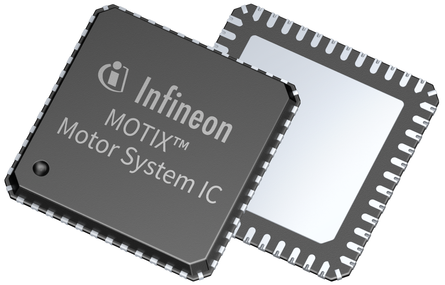
Figure 2: Infineon’s MOTIX Motor System IC.
Efficiency and EMC
One of the challenges of implementing fully solid-state solutions is achieving an optimal balance between electrical efficiency and fulfilling EMC requirements. Optimal load management techniques and soft start/stop on seats and closures using high speed pulse width modulated (PWM) power are common. However, the high-speed switching of the load current can result in challenges with EMC. This leads to the status quo of tweaks and compromises being made through external components or limited configuration options in MOSFET driver registers.
Infineon’s adaptive MOSFET gate control addresses this what is described as a new level of granularity. Not only is it possible to modify the switching slope without affecting the dead time, preserving the widest range of duty cycles and reducing power dissipation, it also allows differing slew rate for both the on and off cycles. Fully configurable through software via the SPI, it allows designers to compensate for the difference in gate drive current required to turn on a MOSFET versus turning it off. The feature is also self-adapting, in that the driver IC recognises and compensates for lot-to-lot variations of MOSFETs.
Comprehensive diagnostics
Another challenge in these motor control applications is differentiating between different failure cases. Shorts to ground or battery, or the case of open load, ideally need to be detected before the MOSFETs are turned on. The MOTIX motor system IC features integrated pull-up and pull-down current sources that detect shorts to battery or ground, as well as the open load case.
A standard integrated safety feature of the driver IC is a watchdog, enabled at power on. During development, it can be disabled, using a specific sequence of commands that ensures it cannot be accidentally turned off during normal operation. In the event of a physical error in SPI communications, such as a shorted signal line, the MOTIX motor system IC enters a fail-safe mode. The SPI communication is monitored continuously for errors. Errors that can be detected range from an incorrect number of bits and protocol errors, such as addressing unused addresses, to clock polarity errors or accesses in fail-safe mode that do not belong to the specified exit sequence. Protection also is enabled when operating in daisy chain mode. Here the communication with the microcontroller is monitored to ensure that data frames are always a multiple of eight bits in length.
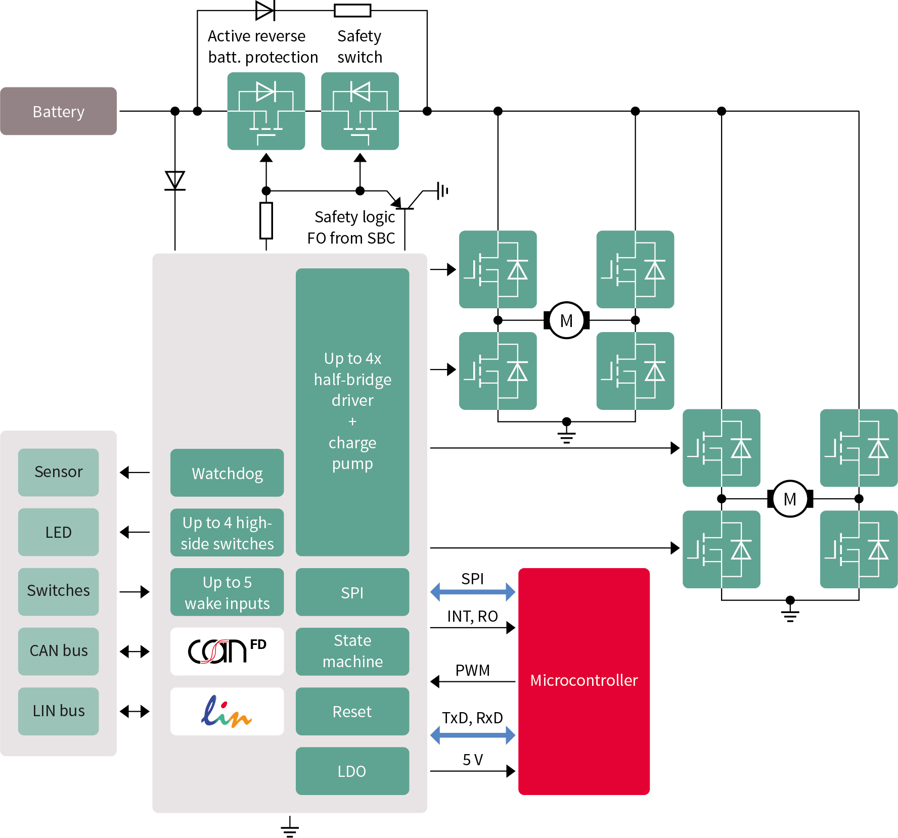
Figure 3: Driver ICs like the MOTIX TLE9562-3QX motor system IC can control up to eight MOSFETs and a reverse battery protection MOSFET.
Internal communication
The power management and internal communication bus transceivers illustrated in Figure 1 are commonly implemented today either discretely or in system basis chips. Here we have a higher level of integration as the MOTIX motor system IC includes a CAN-FD transceiver and a LIN transceiver that conform to the latest automotive standards and OEM requirements. The device also includes a 5.0V, 250mA low drop out (LDO) voltage regulator for supplying the microcontroller as well as the CAN node. There are also up to four PWM inputs, up to five high-voltage wake inputs and up to four low current high-side outputs implemented to supply LEDs, off-board sensors or switch inputs.
The combination of Infineon’s MOTIX motor system IC, MOSFETs and microcontroller provides a higher integration and lower cost solution than implementations of comfort drive control based on current relay-based automotive body controllers. The approach also reduces much of the heavy lifting on the part of engineers and even functional compromises required in some earlier solid-state designs. Such compromises often have to be made when EMC testing at the final phase of development forces adjustments that impact electrical efficiency, resulting in less than optimal performance.

Figure 4: Adjusting seating position is just one of the automated features in a personalised vehicle.