


This article originally appeared in the July’22 magazine issue of Electronic Specifier Design – see ES’s Magazine Archives for more featured publications.
By effectively doubling the number of high-speed electrical interfaces that the module supports (in comparison with a standard QSFP28 module) there comes even greater need to dissipate heat efficiently and effectively. Any failure to do so could compromise the operational performance, reliability, and dependability of these high-speed optical devices. Paul Dawidczyk, Global Telecom/IT Market Sales Manager, Parker Hannifin Chomerics Division discusses.
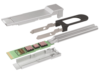
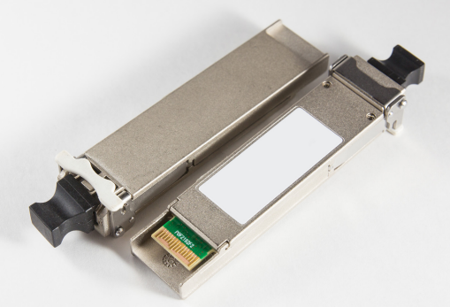
There is no doubt that the advent of data centre network architectures free of bandwidth constraints is thanks to the latest QSFP optical transceiver technologies. The QSFP-DD is a recently introduced optical module and cage/connector system that features an additional row of contacts, thus providing for an eight-lane electrical interface. As a result, the transceiver can operate 25G/s NRZ or 50G/s PAM-4 modulation over 16 pairs of twin-axial conductors or optical fibres to support 200G/s or 400G/s aggregate Ethernet bandwidth.
Higher density, higher heat
For all of their performance benefits, optical transceivers can prove challenging to cool. Air gaps of typically 0.2 to 0.3mm between the module case and cage – and between the cage and PCB – are common. These air gaps are created due to mechanical tolerances and result in inconsistent thermal performance.
QSFP-DD modules are the smallest form factor 400G/s transceivers, offering the highest bandwidth density while providing backwards compatibility to lower-speed QSFP pluggable modules and cables. The 400G/s performance arrives courtesy of highly integrated and advanced PAM-4 DSP chips, externally modulated laser (EML) diodes and GaAs laser diodes. However, this performance does not come without significant thermal challenges. Optical modules get hot due to their use of lasers for transmitting data. Moreover, power loads of up to 25W ensure that design engineers must consider heat dissipation and the application of suitable thermal interface materials.
Time for TIMs (Thermal Interface Materials) Various thermal interface materials are available, including thermally conductive gap filler pads, thermal greases, and thermal gels. These materials improve heat dissipation by filling tiny air gaps and voids between rough or uneven mating surfaces, and through contact with heat generating chipsets.
Thermal impedance is an important property of a thermal interface material. To provide a definition, thermal impedance is a measure of resistance to the flow of heat from a hot surface through an interface material into a cold surface.
As the thermal interface material has a greater thermal conductivity than the air it replaces, thermal impedance across the joint decreases and the component junction temperature reduces. In addition, maximising the contact area between the heatsink and the optical module lowers thermal resistance and improves the system’s ability to cool the transceiver.
Gels, greases, pads
Thermal gels with high thermal conductivity and good flow rate are ideal for robotic dispensing in high-volume applications such as optical modules. With robotic dispensing, it is possible to ensure reliability and consistency, while simultaneously reducing time and costs. Thermal gels are highly conformable, single-component compounds that require no cure. Once dispensed, these advanced gels (which are available in silicone and silicone-free formulations) hold their shape and are perfect for applications where long-term stability is required.
High-performance single-component thermal greases are another good option for automated dispensing where a thinner bond line is required. In short, thermal greases provide low thermal impedance at thin gaps, allowing the use of common heat spreaders.
A further alternative is thermal gap filler pads, which can be die-cut into the exact shape required to provide a highly effective way of dissipating heat from a specific heat-generating component. The soft constitution of thermal gap filler pads also serves to dampen shock loads and reduce vibration stress. As a point of note, although a degree of automated pad placement is possible, the equipment and fixtures required are typically more specialised than those for thermal gels and greases and may not be readily adaptable from one application to the next.
Automate to accumulate
Experience suggests that around 5,000 parts per annum is the threshold when it becomes more economical to use thermal gels and an automated dispensing system. This criteria will almost certainly apply to the majority of optical transceiver applications.
Reputable suppliers of thermal interface materials will be able to provide support with fully automated manufacturing services. Automated production units will dispense the thermal materials – often alongside any requirements for dispensing EMI (electromagnetic interference) shielding materials – before performing automated 100% inspection via a high-specification industrial camera and robot unloading of the parts into suitable protective packaging.
As a point of note, recent advances in thermal gels mean they provide superior performance, greater ease of manufacturing and assembly, and lower cost in certain high-volume applications, particularly as electronic design applications get smaller, denser, and more complex.
A TIM for every application
Regardless of the transceiver design, be it a stacked card cage or belly-to-belly, it is vital to deploy an effective thermal interface between the optical cable connector module and the heatsink attached to the outer case/cage. With speeds of 400G/s now attainable and 800G/s DESIGN: THERMAL MGMT on the near horizon, design engineers must consider the thermal heat dissipation needs of not only the module, but the interface connection on the PCB, as well as at the rack unit or cabinet. Cabinets featuring 40U to 46U racks require immense thermal heat dispersion. Higher data transfer speeds, low latency, and constant availability demand more computing power, which in turn means higher power densities per rack.
Ultimately, the performance and longevity of transceiver lasers depend on their ambient operating temperature. To help maintain this temperature within specified limits, carefully selected and applied thermal interface materials represent the optimal solution. In tandem, designers can reduce thermal spreading losses by keeping the heat sources close to the thermal interface area, and by increasing the thermal conductivity of case materials.
As each new electronic product generation requires higher power in smaller packages, the challenges associated with thermal management become more intense. In all cases, the best way forward is to seek advice from a proven specialist in thermal interface materials, one that can provide support with design, product selection and best-practice manufacturing capabilities.