


Standard unswitched stereo or mono jacks provide a straightforward socket for connecting a set of headphones or low power speakers.
Switched jacks, on the other hand, can be used in a variety of ways, such as to divert audio signals – say from a built-in speaker to externally connected headphones – or to act as an on/off switch, activate an insertion-detection indicator, or to control other functions of the system.
Therefore, with some basic understanding of these functions you can take advantage of a switched jack to avoid designing-in additional circuitry – saving you space, engineering effort and BOM cost.
Switched-Jack configurations
Various configurations are available for switched jacks, with a choice of one or more switches, normally closed or normally open configurations, and isolated switches that have no electrical connection to the inserted plug.
You can identify a suitable switched jack for your application by analysing the schematics presented in the datasheet. Let’s first review the key electrical elements of the jack and associated plug, to understand how they work and how to use them.
Figure 1 shows the plug and jack of a standard stereo audio connector with three conductors. The plug is inserted from left to right, so that the contacts align with each other as numbered. This arrangement provides connections for the two stereo channels, plus ground.
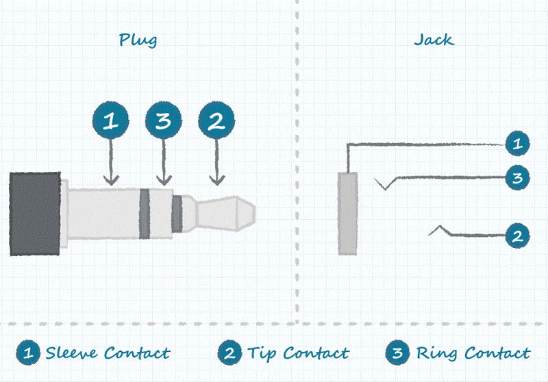
Figure 1. Standard audio plug and jack schematics with terminal nomenclature.
Only a little imagination is needed to see that the contacts in the jack can be arranged so that inserting the plug causes them to move and consequently make or break an electrical connection. Figure 2 shows how this is achieved with a ‘tip-switch’ jack – so called because the switch is associated with the tip terminal.
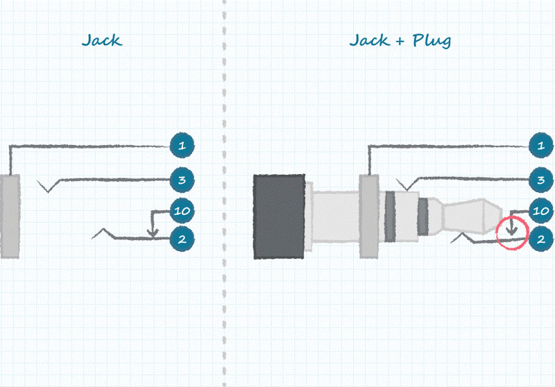
Figure 2. Schematic of tip-switch jack in unmated and mated states.
When the plug is not inserted, the tip terminal (2) is connected to terminal 10. Inserting the plug breaks this connection by pushing the spring away from terminal 10. Hence the status of terminal 10 can be used to determine how the system will respond when the plug is inserted.
With extra contacts, additional switches can be implemented. Figure 3 provides an example. Note that, although the schematic appears more complex, this is transparent to the user: the plug is inserted in the same way, regardless of the number of switches involved.
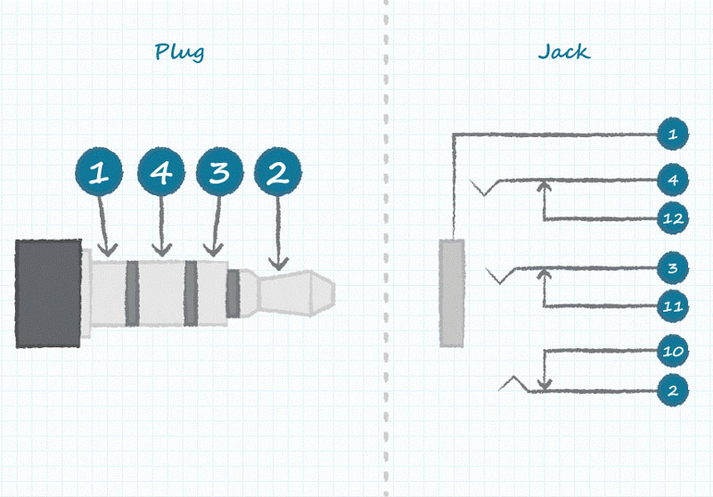
Figure 3. Four-conductor audio plug with three switches.
In addition to the normally closed switches mentioned so far, many other configurations are possible. These normally include Single-Pole Double-Throw (SPDT), Double-Pole Double-Throw (DPDT) and isolated normally open switches, as shown in figure 4. The isolated normally open switch can be used to control other parts of the circuit, for example to activate related functions, illuminate a panel lamp or control a logic signal.
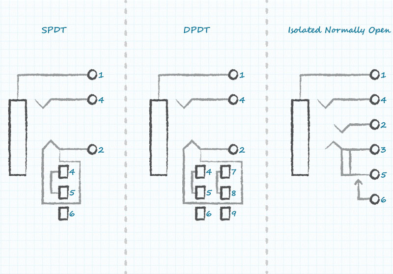
Figure 4. Other switch configurations give designers extra options.
Switched Jack functions and applications
Depending on the number of switches and their actuation, jacks can be used for a wide variety of functions, such as switching audio between speakers and headphones, detecting when the plug is inserted, activating other parts of the circuit on plug insertion, or for use in audio mixing boards.
Figures 5, 6 and 7 suggest practical uses of switched-jack sockets, by illustrating the switch positions in the unplugged and plugged-in states. The same concepts can be applied to solve a wide variety of design challenges.
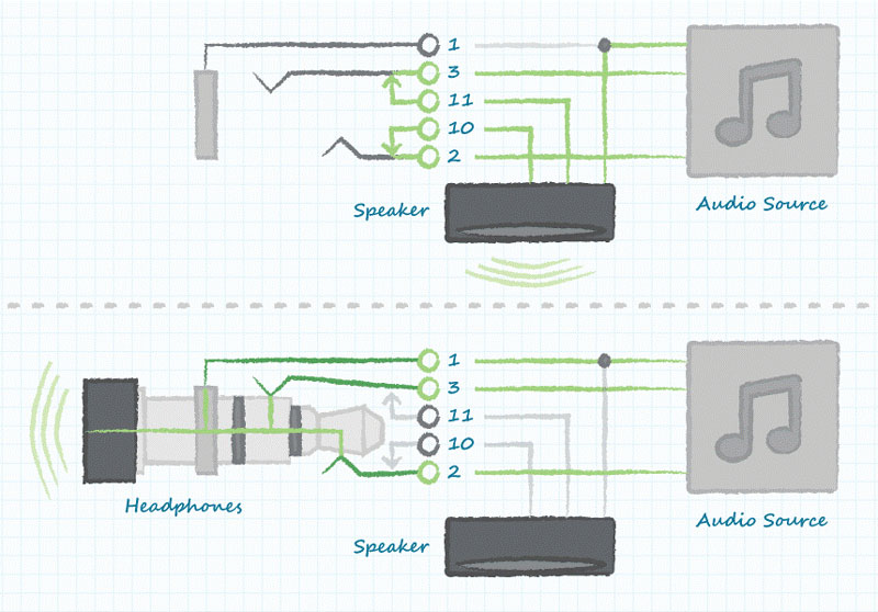
Figure 5. Automatically switching audio channels when the jack plug is inserted.

Figure 6. Activating a light to indicate plug insertion.
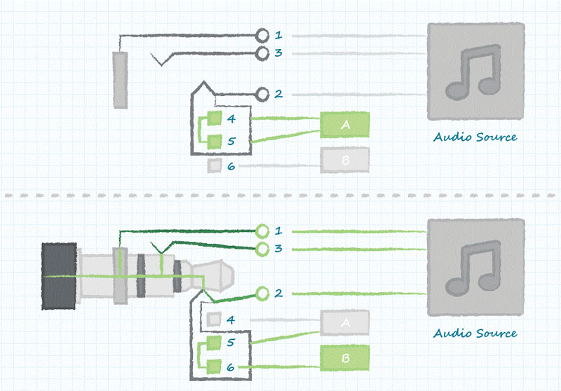
Figure 7. Utilising plug insertion to control other portions of a circuit independent from audio signals.
In the last example, the jack contains a SPDT switch on terminals 4, 5 and 6, which are electrically isolated from the audio signals on terminals 1, 2 and 3. While terminals 4 and 5 are connected when no plug is inserted, inserting the plug connects terminal 5 to terminal 6. Hence, the plug can be used to deactivate one system function and simultaneously activate another.
In addition to offering a variety of switch configurations, CUI Devices’ audio connectors in standard 2.5 and 3.5mm versions are available in various mounting styles such as panel mount, cable mount, PCB through-hole or surface-mount, and horizontal or vertical orientations. Package heights as low as 3mm, and widths down to 5mm, enable use in space-constrained applications.
CUI Devices’ dual 2.5/3.5mm combined jacks are another space-saving option. You can also choose shielded versions to preserve signal integrity in electrically noisy environments, and black, blue, green or pink insulator colour options. The 2.5 and 3.5mm plugs are available in mono, stereo or four-pole configurations.
Additional resources
View more helpful audio connector resources and learn more about our line of jacks and plugs.
Read more helpful ‘how to’ articles on Thermal Management, Power, Interconnect, Audio, and Motion Control from CUI Devices’ Tech Insights blog.