


In a benign environment, that’s no big stretch. So, for example, the connector that attaches to your TV or desktop computer may well have locking screws, but who bothers to screw them down? Well, OK, some of you. But do you get a wrench out, check the connector datasheet and torque down to the exact force specified? Why would you, in truth, it’s not required.
However, what happens when the environment is very far from benign? Not in your living room or office, but on a rocket which will experience high g-forces on take-off, or on an industrial stamping press as part of an Industry 4.0 installation monitoring wear, where consistent vibration is a fundamental part of the operation? There, everything is very different, and the connector – being the most vulnerable item – needs to be as reliable as possible, especially in mission-critical applications where failure is simply not an option.
As well as guaranteeing signal integrity and maintaining physical connection, harsh environment applications require tough connectors for another reason. In an IT application – say in a data centre – it is likely that the equipment will be installed by a qualified electronics technician. In an industrial or defence application, it may be a machine operator or service personnel who unplugs and re-attaches for maintenance purposes. Somewhere in the operating manual (where did I leave that? – never mind) there will be instructions such as: ‘torque down to X Newtons’; ‘use correct tooling’; or simply ‘handle with care’. But how many operators in this situation pay close attention to the manual?
Finally, we should consider DFM (Design For Manufacture). Will the connector need to withstand repeated mating cycles, and is there any way of simplifying or speeding up the assembly process by careful connector selection? It’s actually a very common problem that design engineers only think about what a connector is being used for, and not how it’s actually being fitted together. A key lesson is always to think about the production process.
It is for these reasons that manufacturers have introduced specific products that have been engineered to withstand these challenges. Two examples from Harwin are the M300, and the recently-launched Kona family.
M300 connectors deliver reliable performance in harsh environments such as aerospace, defence, and industrial applications. The compact connectors deliver up to 10A per contact, providing a lightweight, robust solution with a proven track record under extreme conditions. These 3mm pitch PCB connectors are fitted with stainless steel jackscrews to ensure that terminations are not affected by vibration and shock.
Want to know just how strong these connectors are? Click here for a video of your author abusing an M300 connector (Figure 1) with a mallet in a way that is definitely not recommended in the datasheet but proves the ruggedness of these devices. OK, it’s a bit of fun, but the point is made.
 Figure 1
With an 8.5mm pitch and individually shrouded connections, Kona family connectors (Figure 2) allow designers to specify high current for maximum power in extreme conditions, enabling systems to handle up to 60A and 3000V per contact. The high-quality connectors are available in 2, 3 or 4 pin counts, in a compact single-row configuration.
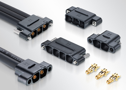 Figure 2
Vibration and shock resilience are built into the design, with six-finger beryllium-copper alloy contacts ensuring electrical continuity and good spring force properties. The tough resilient housings protect the connections from physical knocks and damage. Male pin connectors are of a through-board PCB mount design with additional board fixings for strain relief. Female cable housings are supplied with thumbscrews fitted. Female cable contacts are ready for 8AWG cables to be soldered before assembly to the housing. As is shown in this assembly video (Figure 3), the robust housing helps with blind mating, and the socket-head screws enable the use of ball-head screwdrivers which permit angular operation, also simplifying blind mating.
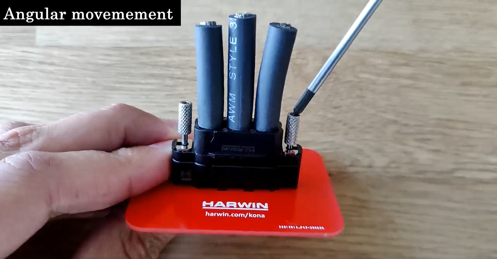 Figure 3
Let’s take a look at a couple of common use cases.
A three-pin M300 connector can be used to hook up a panel mount potentiometer. Panels are often built using a modular construction, where, during final assembly on the production line, they are connected by hand. The enclosure panel, PCBs, and other component parts such as power supplies, and sensors are all connected together by hand, so having a robust connector such as the M300, especially if supplied as a cable assembly, will help avoid damage during production (Figure 4).
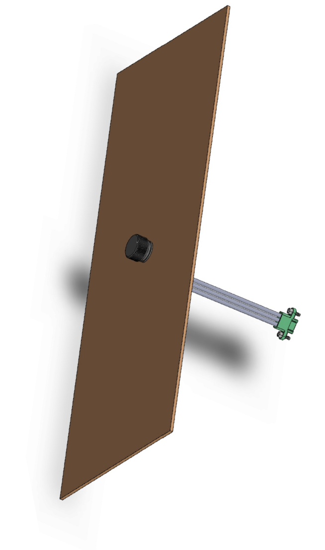 Figure 4
Another example can be observed when considering DC/DC converters, which, quite often, rely on a cheap terminal block. For high reliability applications this may not be sufficient, and it would be more appropriate to use a four-way Kona connector, or even two two-way Kona connectors (Figure 5).
 Figure 5
In both these examples, if a cheap connector were to be specified, then a trivial accident on the shop-floor, or – worse – a condition caused by the environment when in operation, could render an assembly or piece of equipment that costs thousands of dollars totally useless.
When it comes right down to it, the humble connector that design engineers often consider last (if at all) is actually very vulnerable, due to its mechanical as well as electrical function, and also because it is the one component that personnel with varying degrees of training and aptitude handle on a regular basis. By being proactive and risk-adverse, the designer can increase product reliability and make a lifelong friend of the production and maintenance staff.