


By Jeff Smoot, Same Sky
Their circular housing geometry enhances mechanical robustness, making them well-suited for environments subject to vibration, shock, temperature fluctuations, electromagnetic interference (EMI), and ingress from dust, moisture, or gases.
Available in a wide spectrum of formats, circular connectors span from general-purpose plastic and metal housings to specialised variants such as DIN, metric, hermetic, push-pull, keyed, and micro/nano connectors. hybrid models consolidate power, signal, and data transmission in a single connector, while modular and custom-configurable options allow for precise adaptation to application-specific electrical and mechanical requirements. This article will dive further into standard circular connectors and cables, including their underlying construction, codes and designations, key selection criteria, and more.
Circular connector basics
The cylindrical geometry of circular connectors provides an inherently high strength-to-weight ratio, offering superior mechanical durability compared to other form factors. This structural advantage translates to enhanced resistance against environmental stressors, mechanical shock, accidental decoupling, and frequent mating cycles, making circular connectors ideal for high-reliability or ruggedised applications.
Pin count and contact arrangements vary by use case, with keyed or asymmetrical configurations ensuring proper orientation and secure mating. These design elements reduce the risk of misalignment and enable consistent electrical connectivity.
Threaded coupling mechanisms are the most common method for securing circular connectors, utilising screw-on shells to ensure a reliable connection that withstands vibration and impact. However, alternative locking systems – such as bayonet, push-pull, and snap-lock – are also available to support quick-disconnect or tool-less installation in various field environments.
The core structural elements of a circular connector are further broken down as follows:
- Contacts: these consist of male pins and corresponding female sockets that form the electrical interface. Contact materials and plating are selected based on current-carrying capacity, contact resistance, and durability
- Insulator (dielectric insert): serves as a non-conductive medium that holds the contacts in fixed positions and maintains electrical isolation between pins and between the contacts and connector shell
- Shell: the outer housing provides mechanical protection, EMI shielding (in metal variants), and alignment features for proper mating. It also facilitates mounting or integration into panels and devices
- Accessories: these include mechanical and sealing components such as backshells, grommets, keys, O-rings, strain relief clamps, and sealing gaskets – each contributing to ingress protection, mechanical stability, and reliable cable termination
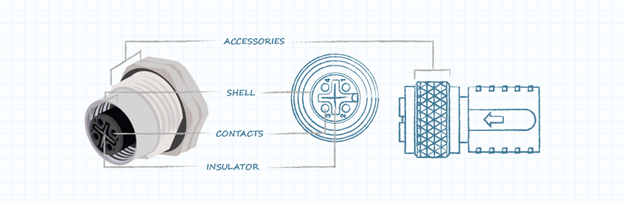
Figure 1: General construction of a female circular connector
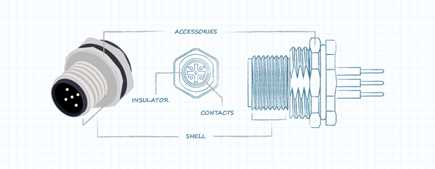
Figure 2: General construction of a male circular connector
Codes and designations
M-style circular connectors are standardised interconnects commonly deployed in industrial automation systems for linking sensors, actuators, and field devices. These connectors are engineered for reliable operation in harsh environments, offering resistance to vibration, moisture, dust, and extreme temperatures. The ‘M’ designation corresponds to the metric thread size of the coupling nut and mating interface – defining the physical size of the connector:
- M5: 5mm thread diameter
- M8: 8mm thread diameter
- M12: 12mm thread diameter
To prevent mis-mating and to support application-specific requirements, circular connectors are further categorised by coding types, which dictate pin configuration, keying geometry, and supported protocols.
- A-coded: used for sensors, actuators, 24Vdc power, and 1Gbit Ethernet. Most prevalent in general-purpose sensor connections
- B-coded: supports Fieldbus and Profibus systems – digital communication protocols used in industrial process control and distributed I/O
- C-coded: features dual keyways for enhanced mechanical security; typically used for ac power distribution to field devices
- D-coded: rated for 100Mbit Ethernet and Profinet systems, suitable for time-sensitive industrial networking applications
- X-coded: designed for high-speed data transfer up to 10Gbit Ethernet and supports Power over Ethernet (PoE); includes enhanced shielding for EMI performance
- S-coded: used for ac power delivery, serving as a modern replacement for legacy C-coded designs
- T-coded: used for 24V dc power delivery, offering improved current handling and safety over legacy A-coded power connectors
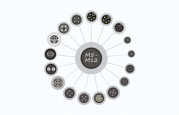
Figure 3: Common interface options for M-style connectors
Selection guidelines for circular connectors
When specifying circular connectors for a new design or redesign, engineers must consider a broad range of electrical, mechanical, and environmental parameters to ensure optimal performance and reliability. One of the primary decisions is whether to use a circular plastic connector (CPC) or a circular metal-shell connector (CMC), each offering different trade-offs in terms of ruggedness, cost, and environmental resistance.
The connector’s gender is a fundamental characteristic, where the male version contains contact pins that mate with sockets in the female receptacle. In most cases, connectors are sourced as mated pairs within the same product family or manufacturer, as cross-compatibility between different brands is uncommon. Another key factor is the number of contacts required to accommodate all signal, power, and data transmission needs of the system.
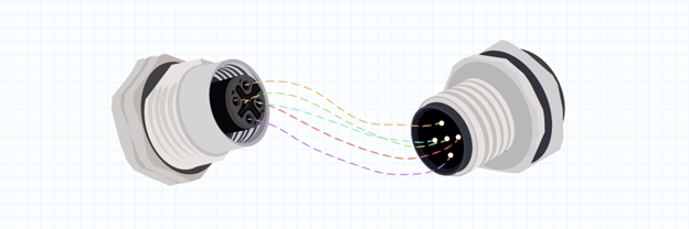
Figure 4: Ensure you source mating compatible male and female circular connector pairs
Engineers must also determine the termination method used to bond the wires or cables to the connector contacts. Options include soldering, crimping, wire wrapping, or lug terminations, each with implications for ease of assembly and long-term reliability. The contact size corresponds to the wire gauge and affects both current-carrying capability and insertion force. From a performance standpoint, the connector’s voltage and current ratings must match or exceed the electrical demands of the application, with current specified in amperes (A) and voltage in volts (V).
Insertion frequency, often defined in terms of mating cycles, is another critical parameter. Applications involving frequent connect/disconnect operations may require connectors with reinforced contact materials and protective backshells to ensure long-term durability. Similarly, the mounting style, whether cable-mounted, panel-mounted, or PCB-mounted, will influence mechanical integration and require specific hardware or design accommodations.
The locking mechanism or coupling style dictates how the connector halves engage and stay mated under mechanical stress. Threaded, bayonet, push-pull, latch, and quick-disconnect options are available, each suited to different operational environments. Additionally, the backshell type must be selected to manage strain relief and sealing on the cable entry side. Straight, right-angle, crimped, or environmentally sealed backshells are common, depending on routing constraints and protection needs.
Environmental conditions also heavily influence material selection and accessory needs. Factors such as exposure to moisture, dust, EMI/RFI, chemicals, or mechanical impact will drive decisions regarding connector materials, sealing features, and optional accessories. For instance, stainless steel or aluminum housings may be needed for harsh industrial environments, while plastic or composite materials may suffice in low-risk applications.
Accessories such as gaskets, strain reliefs, sealing boots, dust caps, flanges, and cable grips further enhance the connector’s functionality and protection. These elements are especially important in maintaining ingress protection (IP) ratings and supporting cable integrity over time. Lastly, it’s important to note the terminology around plugs and sockets: plugs are typically associated with cable-side connectors, while sockets or jacks are usually panel-mounted. However, naming conventions may vary slightly by manufacturer.
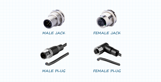
Figure 5: Typical jack and plug gender designations
Conclusion
When selecting a circular connector for harsh environments, several environmental and electromagnetic considerations must be evaluated. Will the connector be exposed to moisture, dust, chemicals, or subject to full or partial immersion? Does the application require shielding against electromagnetic interference (EMI) or radio-frequency interference (RFI)? Will the connector be installed in a system that experiences high vibration, mechanical shock, or frequent impact events? The answers to these questions will directly inform the selection of materials, sealing methods, locking mechanisms, and optional accessories.
Despite these challenges, circular connectors remain one of the most robust and versatile interconnect solutions available, particularly for demanding industrial and field-based applications. Their geometry, mechanical strength, and broad range of available configurations make them well-suited for maintaining signal and power integrity in adverse conditions. Same Sky offers a comprehensive portfolio of circular connectors and cable assemblies specifically engineered to withstand these environments and deliver reliable performance across a wide range of use cases.