


This article originally appeared in the March ’22 issue of Electronic Specifier Design– see ES’s Magazine Archives for more featured publications.
However, mmWave’s advantages for 5G communications are partially offset by several technical challenges. For starters, mmWave does not propagate very far — mmWave transmissions are easily absorbed by the atmosphere and do not penetrate trees, building walls, and other infrastructure. Accurately measuring the performance of mmWave devices with over-the-air (OTA) test equipment and methodologies is also difficult. The wide bandwidth of mmWave — which is such an attractive feature for 5G communications — also degrades the signal-to-noise (SNR) because the energy from the signal spreads across the bandwidth. Finally, mmWave uses higher-order modulation schemes to improve spectral efficiency, which in turn requires improvements in error vector magnitude (EVM) performance.
As signal strength decreases, noise from the test system being used to measure it will also reduce the SNR, impacting results. Therefore, signal analysers are designed to handle multiple types of test applications, including high- and low-power modes, narrowband and wideband signal modes, spectrum, or vector modes. This versatility introduces many possible components into the signal path, though, including low noise amplifiers (LNAs), preamplifiers, attenuators, preselection filters, and others. Applying or adjusting some of these components can improve measurement accuracy for different test scenarios. This article examines some of the technical challenges posed by mmWave frequencies and the difficulties these challenges pose to making accurate, repeatable measurements.
The article also suggests strategies for improving measurement accuracy with a signal analyser by utilising different signal path settings.
Path loss
Excessive path loss is among the most vexing and commonly cited challenges to 5G mmWave communications. Path loss between the device under test (DUT) and the measurement equipment decreases the SNR, making it difficult to make accurate measurements for metrics, such as error vector magnitude (EVM), adjacent channel power, and spurious emissions.
Compounding the issue, the small size of components and antenna arrays eliminates the possibility to place probes for conducted tests, necessitating the use of OTA — or radiated — test. The OTA testing requirement, combined with the excessive signal path loss of mmWave transmissions, requires control and calibration of the radiated environment around the test setup.
Offsetting signal path loss requires flexible signal analyser hardware and software that enable the creation of the optimum solution for a specific signal and measurement. For example, a signal analyser can apply attenuation at higher power levels or a preamplifier at lower power levels to measure a variety of input signals. Signal analysers provide several RF signal paths to lower noise, improve sensitivity, and reduce signal path loss.
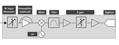 A signal analyser block diagram
Measuring low-level signals (default signal path)
By default, in the signal analyser’s standard signal path, the input travels through the RF attenuator, preamplifier, and preselector before reaching the mixer. This signal path is ideal for measuring low-level signals that have a bandwidth of less than 45 MHz.
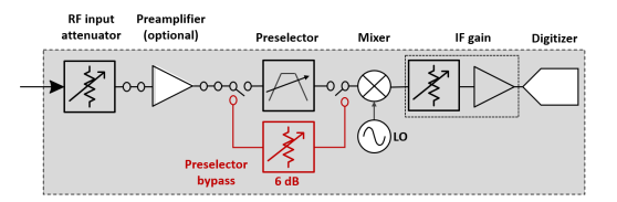 A microwave preselector bypass
Analysing wideband vector signals (microwave preselector bypass path)
mmWave wideband signals can be particularly challenging to measure. Bypassing the signal analyser’s preselector is a good option when increasing the RF analysis bandwidth to analyse wide-bandwidth vector signals, because it allows wide-bandwidth signals to pass unimpeded through the RF chain. Not only does bypassing the preselector enable wideband analysis, but it also removes the amplitude drift and the preselector’s passband ripple, further improving the overall accuracy of the measurement.
Improving modulation analysis (low-noise signal path)
The low-noise signal path is well suited for making EVM measurements and other measurements that test transmitter modulation quality at higher power levels. Since the gain of the amplifier, frequency responses, and insertion loss are compounded at higher frequencies, bypassing the lossy switches in the preamplifier path and the preamplifiers provides the optimal RF signal path. This path reduces path loss and the frequency responses and noise created by the preamplifiers and switches. Choosing this signal path for wideband EVM measurement results at higher frequencies increases measurement sensitivity and improves signal fidelity.
Wideband modulation analysis (full-bypass signal path)
A full-bypass signal path reduces path loss, improves signal fidelity, and increases measurement sensitivity. A full-bypass signal path can reduce loss at mmWave frequencies by up to 10 dB compared with the default signal path.
The full-bypass signal path is a combination of the low-noise signal path and the microwave preselector bypass path, avoiding multiple switches in the low-band switch circuitry as well as the microwave preselector. While the advantages of using the full-bypass path are clear, this path has a few drawbacks, including potential in-band imaging and low SNR for testing low-power signals. However, eliminating images in the band of interest by adding a bandpass filter can improve EVM results by 1 to 2 dB. An external preamplifier can also enhance the SNR when testing low-power signals.
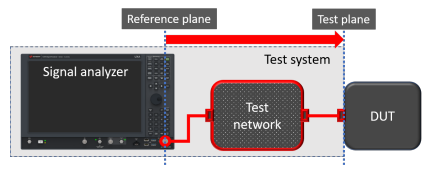 All the test network elements must be taken into consideration
Other considerations
Another critical element that impacts the accuracy of 5G mmWave measurements is the input mixer level. The input mixer-level setting of a signal analyser offers a trade-off between distortion performance and noise sensitivity. As discussed above, SNR is decreased in 5G mmWave signals due to wideband noise and excess path loss, leading to poor EVM and adjacent power ratio measurements that do not represent the actual performance of the DUT. The signal analyser’s input mixer is another tool that can help overcome the challenges of 5G mmWave frequency measurements. The optimum mixer-level setting is dependent on the measurement hardware, input signal characteristics, and specification test requirements. It is also possible to apply an external low-noise amplifier (LNA) to the signal analyser’s front end to optimize the mixer’s input level. Some new signal analysers such as Keysight’s N9042B UXA X-Series signal analyser include a LNA in the signal path, along with the preamplifier. This allows users to achieve the benefits of using a LNA to optimize the mixer’s input level without requiring external components.
To get the best EVM measurement results, the intermediate frequency (IF) noise of the signal analyser must be low enough that it does not further decrease the SNR. The input signal to the digitizer must be high enough, yet not too high that it overloads the digitizer. The optimum balance is a delicate dance that requires a combination of RF attenuator, preamplifier, and IF gain value based on the signal peak level. New signal analysers enable users to optimize these hardware settings at the touch of a button, improving SNR while avoiding digitizer overload. However, manually tweaking settings such as IF gain and RF attenuators is often necessary for the optimum settings, yielding the best measurement results.
Components in the signal path
Another critical factor to consider for making accurate 5G mmWave measurements is the impact of components in the path between the signal analyser and the device under test (DUT). The components in the signal path can degrade the signal analyser’s overall measurement accuracy.
Measurement accuracy becomes even more critical as bandwidths grow wider and frequencies rise into the mmWave spectrum. With smaller margins for error, engineers need to find ways to eliminate frequency response errors, which occur at different frequencies and impact phase and amplitude responses. Signal analysers provide an internal calibration routine to correct their frequency responses.
Cables, connectors, switches, and fixtures in the signal path between the signal analyser and the DUT can degrade measurement accuracy because of frequency response errors. Using different amplitude correction configurations and complex corrections can help remove frequency responses, providing a more accurate picture of the DUT performance.
Signal analysers enable the configuration of both amplitude and complex corrections to correct frequency responses (although a high-performance signal generator or a vector network analyser is required to calibrate the test network). Using a signal generator in combination with a power meter and sensor to measure amplitude, then inputting the correction values into the signal analyser, is an effective method for making amplitude corrections. New receiver calibrators that are specifically designed for signal analyser receiver measurement systems, such as Keysight’s U9361 RCal receiver calibrators, provide a transfer standard enabling both absolute amplitude and complex magnitude and phase corrections.
Making accurate measurements for 5G at mmWave frequencies
The promise of 5G — especially the mmWave FR2 band of 5G — is clear. It provides a step function increase in speed, bandwidth, and performance and will ultimately enable entirely new use cases and business models. But working with mmWave frequencies presents obstacles, particularly in terms of path loss, that make it challenging to make accurate, repeatable measurements. Understanding and utilizing the various RF signal path options on your signal analyser can help you overcome these challenges when making 5G mmWave measurements.