


Minimising the oscilloscope probe ground loop
The magnitude of ripple and noise in the power supply output is usually only a few millivolts and can be obscured or distorted by unwanted internal signals or noise picked up from external sources. This can be prevented by taking care to set up the probe correctly.
The key to accurate measurements is to minimise the ground loop created by the probe and its return path because the inductance in this loop can amplify internal signals and pick up external noise. While the ground lead and alligator clip of a typical standard probe are easy to use, they create a relatively large ground loop that can couple noticeable distortion onto small measurements.
However, the ground loop can be minimised by adapting the probe. Two popular ways to do this are the ‘tip and barrel’ method or the ‘paperclip’ method.

A typical standard probe has a long ground lead that causes a large ground loop
The tip and barrel method involves removing both the ground lead and the probe cover near the tip. Removing the probe cover exposes the barrel. Then, when probing the output voltage with the tip, the exposed metal of the barrel needs to be held in contact with a nearby ground connection.
Although ground-loop problems are minimised, finding a location to contact the output voltage and ground the barrel at the same time may be difficult. Moreover, such a point may be some distance from an output capacitor, which is also not ideal. The output voltage should be contacted as near to the output capacitor as possible.
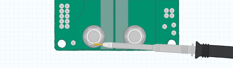
Tip and barrel method in practice
The paperclip method also involves removing the ground lead and exposing the barrel. A small coil of wire is then wrapped around the barrel and formed to create a short ground electrode. This combines the advantage of a small loop area with extra flexibility to find a suitable location to probe the output voltage and make a ground connection, close to an output capacitor.
Alternative techniques are known, and engineers may have their favorites, but the most important goal is to keep the ground loop as short as possible.
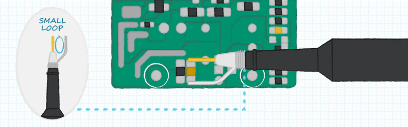
The paperclip method can ease probe positioning
Test conditions for ripple and noise
Using these enhanced oscilloscope probing methods, it is possible to measure the power supply ripple and noise accurately. Ripple describes a small AC component present in the power supply output voltage, resulting from internal switching. Noise refers to high frequency spikes in the output voltage caused by parasitic inductances.
Ripple and noise as stated in the datasheet are usually taken at full load and so must be measured under the same load conditions. However, loading is not the only factor that influences ripple. The input voltage also has an effect, so all voltages of interest should be measured.
In addition, some manufacturers specify external capacitors that should be added to the output for the purposes of the measurement. This is typically an electrolytic capacitor of about 10µF and a ceramic of 0.1µF. The measurements can usually be taken using a single probe placed close to these capacitors, where the oscilloscope channel bandwidth is typically specified to 20MHz.
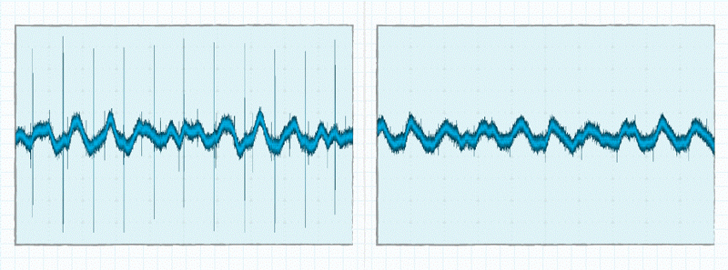
Comparison of probe measurements taken with large ground loop (left) and the ‘paperclip’ method (right)
Transient response and test conditions
Transient response refers to the deviation in the output voltage when the load suddenly increases or decreases. The power supply cannot react instantaneously and either has too much stored energy as the load reduces, or not enough if the load is increased. The output capacitance absorbs excess energy, causing the output to increase, or discharges energy into the load resulting in a decrease in voltage.
Although it takes several switching cycles, the power supply will adjust to the new load and the output voltage will stabilise at its nominal value. Hence, the power supply’s transient response is characterised by the magnitude of the deviation from the nominal output voltage and the time taken to recover, or return within the specified regulation limits.
Whereas the ripple and noise for a given power supply are affected only by the loading and input voltage, transient response is subject to a number of additional factors including the slew rate of the load transient, the starting current, and the ending current. The faster the slew rate, the more the output will deviate before the power supply reacts to stabilise the voltage. The beginning and ending current levels are also important because power supplies often behave differently at light loads.
A transient that crosses between one region and another may cause the power supply to change its operating mode, with an attendant effect on the transient response. Therefore, when measuring the transient response, it is important that the start current, end current, and slew rate match the specified conditions.
2-channel measurement of transient response
Two scope channels are needed for measuring transient response. One probe is connected across the output, and should be placed close to the output pins or regulation point to prevent any voltage drop in the output cabling causing a dc offset between the two loading states. The second probe is needed to monitor a signal synchronous to the load transient, such as the output current, which is used as a trigger to make the scope display the output voltage deviation.
![]()
Transient response measurement triggered by load-current signal (lower trace)
Conclusion
To make a detailed evaluation of a power supply, an engineer needs to understand ripple and transient, and how to measure both accurately. When using an oscilloscope, suitable probe measurement techniques should be used to minimise the ground-loop area to exclude unrelated noise and distortion.
In addition, it is important to understand that the results can only be compared with the manufacturer’s specifications if the test conditions described in the datasheet have been applied properly.