


Artificial intelligence (AI)-focused CPUs, GPUs, FPGAs or system scale ASICs, collectively known as XPUs, use high-end ICs with multiple cores and billions of transistors. They consume many hundreds of amps and present the power-system designer with significant challenges. Engineers creating high-density, power-hungry systems-on-chip can simplify the power-delivery part of their project with Power-on-Package (PoP). This tool brings the critical final stages of the power chain right onto the XPU’s substrate (see Figure 1), and unlocks benefits for performance and efficiency.
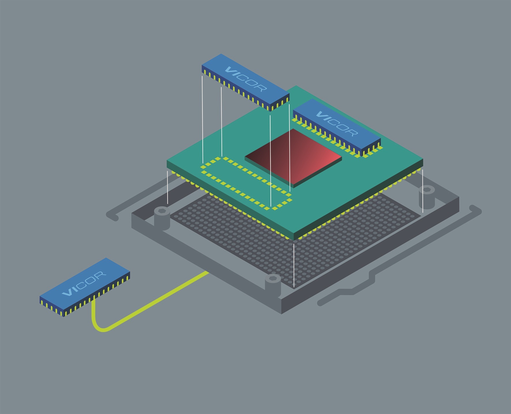 Figure 1: The Power-on-Package solution restructures the final stages of XPU power provision
As semiconductor technology has evolved, the power requirements for devices such as processor cores have changed dramatically. Core voltages have reduced from 5.0 to 3.3V, then to 1.8V and now to sub-1.0V levels. The corresponding reduction in feature size enables more and more logic to be placed on a chip, so much so that many complex devices are thermally-limited. The amount of heat the package can dissipate sets the upper boundary of what can be placed in the chip. With thermal design power (TDP) often well in excess of 100W, the amount of input current required has increased dramatically as the supply voltage has fallen, and current specifications of several hundreds of amps are no longer exceptional. Conventional practice is to power XPUs with multi-phase regulation from a 12V distribution bus, but providing hundreds of amps in this way is extremely challenging.
Voltage increases
As supply voltages have declined, the required quality of the power delivered has increased. Since logic switching margins make up a higher proportion of the very low supply voltage, the supply itself must be very stable and produce very little noise in order to eliminate the possibility of voltage transients that cause false triggering. With currents in the hundreds of amps, even the smallest resistance in the power supply path can lead to unacceptable voltage (I²R) drops. The same effects acting along the complete supply path generate further undesirable losses. Additionally, XPUs frequently gate complete processor cores or other large segments of logic on and off in nanosecond timescales, generating large steps in demanded current that the supply scheme must be able to satisfy without unwanted transient effects.
PoP represents the convergence of distinct but related trends in power supply design. These are the separation of voltage transformation and regulation functions, and the gradual movement of the last stage of power systems closer to the point-of-load. In pursuit of more efficient and higher-performing power systems, Vicor has developed modules and evolved its Factorized Power Architecture (FPA) to result in today’s PoP. This makes the use of FPA in high-performance supercomputing applications possible, says the company.
Factorised power allows the distribution of higher-voltage power, typically 48V, around a system and on the motherboard with single-stage conversion from that value to the point of load. In conventional industrial solutions, such a high conversion ratio is difficult to achieve. Vicor has developed a topology called Sine Amplitude Converter (SAC), which enables very high ratios to be efficiently realised, with both low losses and noise. In the SAC layout, power MOSFETs switch only at voltage and current zero-crossing points, all but eliminating switching losses. Switching frequency can also be high, minimising the need for output filtering capacitance.
In PoP, a module called a modular current multiplier, or MCM, is placed directly on the substrate that carries the XPU silicon. As the name suggests, the MCM performs the single function of a fixed-ratio DC/DC converter (effectively a DC transformer). It generates the low voltage and high current needed by the silicon from a lower current and higher voltage feed that arrives via the XPU substrate/package pins, and that is delivered across the substrate or PCB on which the XPU resides. This arrangement produces several clear benefits. Firstly, the highest peak current is the path from the modular current multiplier to the XPU, secondly, very low resistance in this path produces correspondingly low I²R losses and finally, very low inductance on this path aids the transient performance of the MCM.
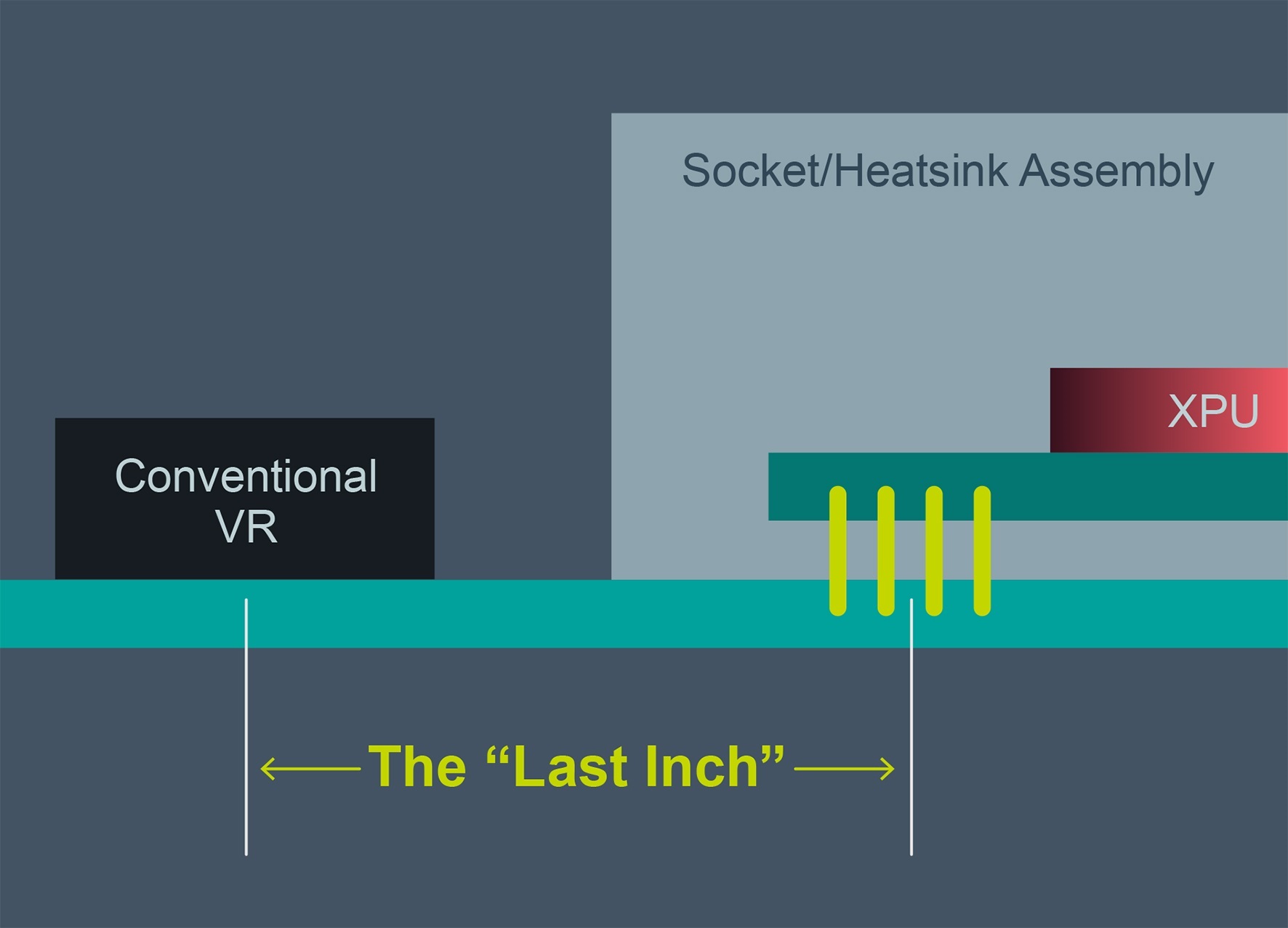 Figure 2. a) Conventional final stage of core-voltage regulation, with a point-of-load regulator close to the target device, but mounted on the host PCB;
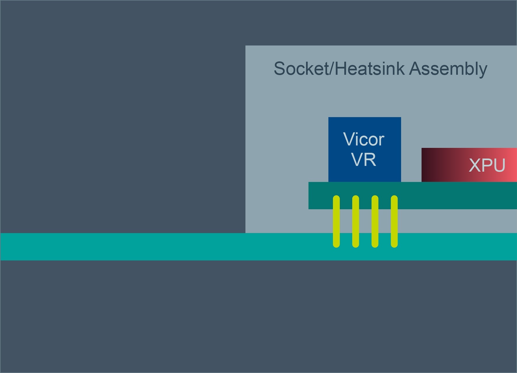
Figure 2b: b) the PoP solution, where regulation and conversion moves on to the XPU substrate
This is the domain referred to as the “last inch,” the final few millimetres in the power path to the XPU, shown in Figure 2. Conventionally, last-inch copper traces and package pins might present a few hundred µΩ of resistance. For a high-end XPU drawing 200A, a 500µΩ path would result in a drop of 100mV – more than 10% of the sub-1V supply rail. Even more troubling, the I²R loss in this example implies an additional 20W of heat generated in the vicinity of the XPU. To overcome these obstacles, the PoP approach places the MCM on the device’s package, which allows all of the power feed to the XPU delivered via the motherboard to remain at higher voltage and reduced current levels. Losses on the PCB itself are thus reduced, and copper can be saved in PCB power planes.
The only way to provide a sufficiently low-impedance path in the absence of an on-substrate converter is to allocate many pins to core power provision. By placing the MCM directly on the XPU substrate, however, power delivery from the PCB to the XPU package carries currents typically 1/50th of the value needed to supply the core. This reduces the number of pins dedicated to power on the XPU package by as much as 10x.
As in a traditional FPA design, the PoP system places a pre-regulation stage upstream of the current multiplier: an MCM Driver module, or MCD, which is mounted on the motherboard PCB. PoP re-integrates the PRM and VTM functions within the MCD and MCM modules retaining the FPA. For even higher regulation accuracy, feedback can be taken from the output of the final conversion stage to control the PRM.
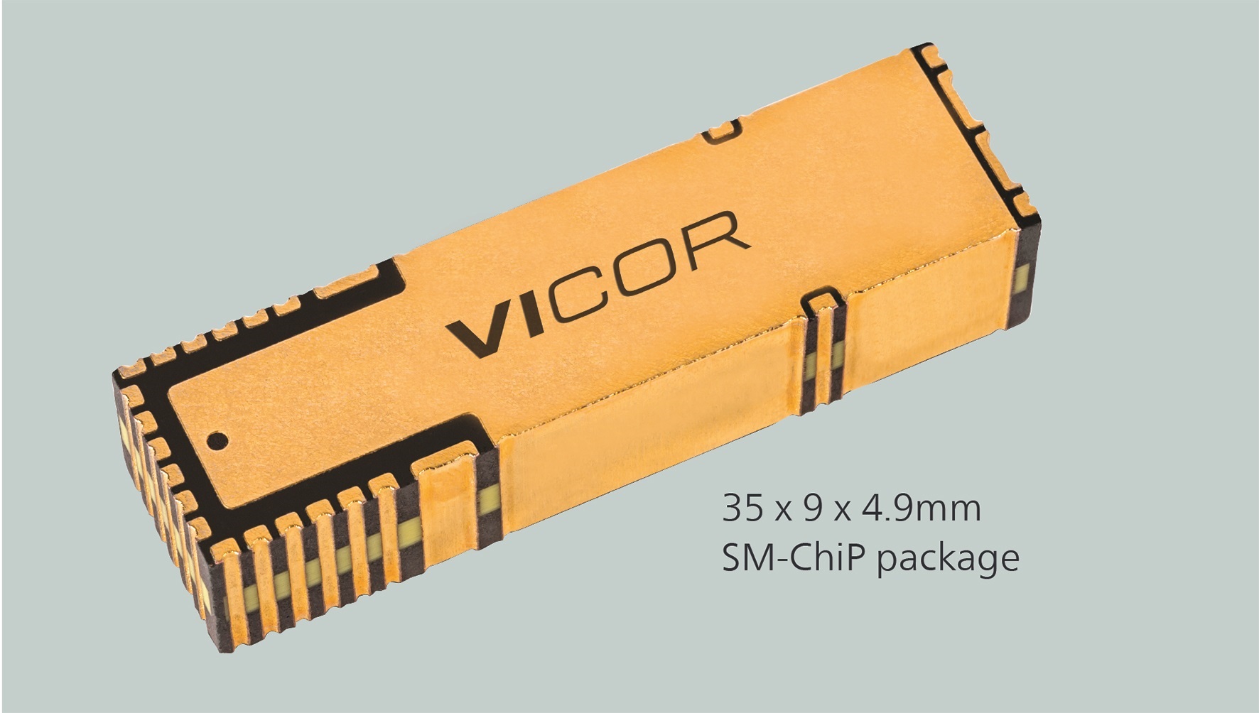 Figure 3: The SM-ChiP package uses laminated construction and direct surface-mount interconnection to the XPU’s package substrate and lead frame
To provide a suitable physical format for mounting on the XPU substrate, Vicor configured the SM-ChiP package (Figure 3), further developing techniques employed in its VI Chip modules. The SM-ChiP uses a surface-mount construction with minimal-impedance terminations to the substrate (or motherboard). The MCM3208S59Z01A6C00 module measures 32 x 8mm and 2.7mm high. A pair will supply 2 x 160A continuous, or 2 x 320A peak current, fed by an upstream MCD3509S60E59D0C01 MCM driver module (35 x 9 x 4.9mm) on the host PCB that is capable of 400W average power and 600W peak. For even higher currents, twin MCM4608S59Z01B5T00 modules (46 x 8 x 2.7mm), each rated for 300A continuous and 500A peak, allow a system to reach a peak-current figure of 1kA. The accompanying MCM driver MCD4609S60E59H0T00 (46 x 9 x 4.9mm) mounts on the motherboard and provides 650W average/1000W peak.
Supercomputing power
The high-current demands imposed by the latest generations of supercomputers call for a re-thinking of power delivery. Now, where a single inch of distance from the regulator to the XPU is a critical factor in power loss, PoP enables high-efficiency and high-density power delivery critical to high-power XPUs. It also eliminates the barriers found in conventional power solutions by using a higher distributed voltage (48V) and enabling final-stage voltage transformation directly adjacent to the XPU, which effectively removes the last inch.
 Figure 4: The liquid-cooled Gyoukou ExaScaler/PEZY ZettaScaler-2.2 supercomputer
The Gyoukou ExaScaler/PEZY ZettaScaler-2.2 supercomputer (Figure 4) is located at the JAMSTEC Yokohama Research Institute in Japan. In one of the regular updates that rank the world’s installed supercomputers it was assessed in November 2017 at position number five in the Top 500 ranking by processing throughput. It reported as 19.1PFlop/s (1015 floating point operations per second). It was also ranked number four in the Green 500 ranking, which is based on energy consumed relative to processing power, for its 14.1GFlops/W performance rating.
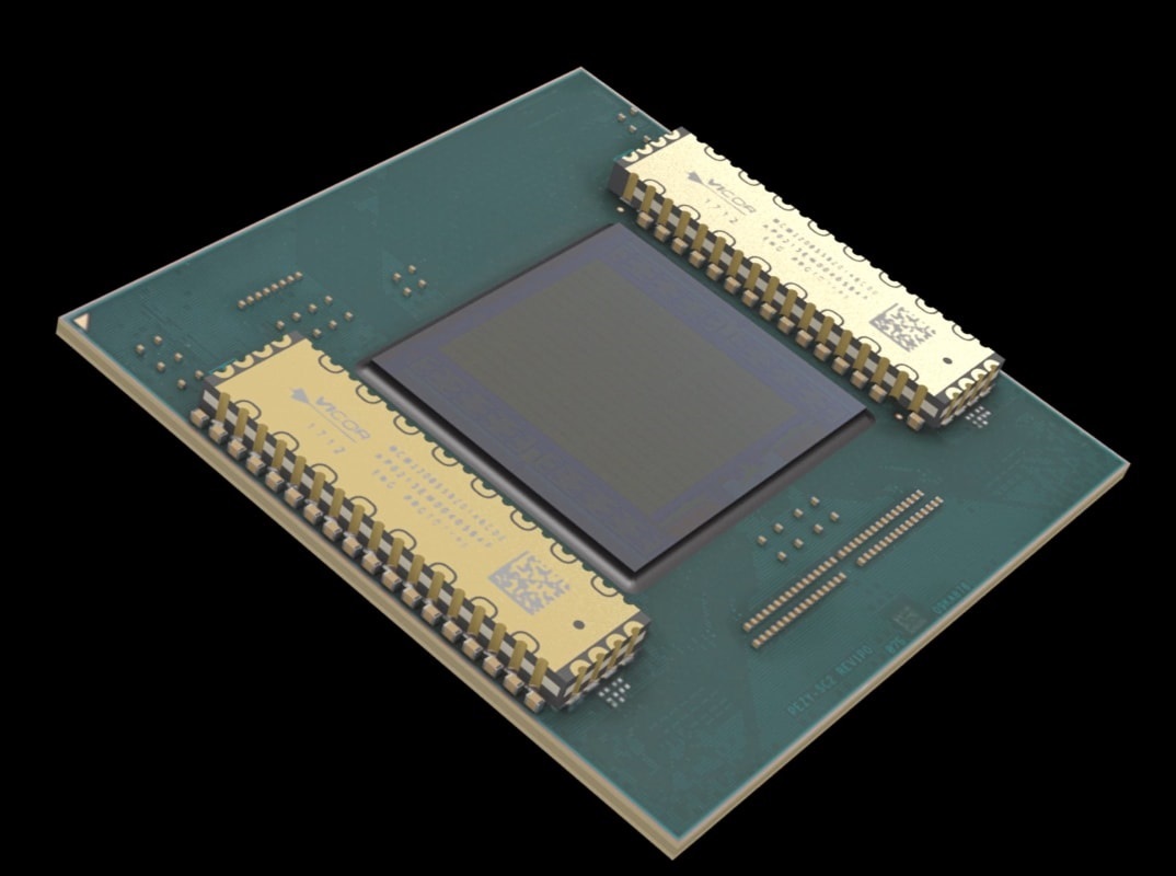 Figure 5: Vicor MCM current multipliers sit next to the XPU silicon on the Gyoukou ExaScaler’s core computing element
As with many other supercomputer designs, thermal design is a key part of the machine’s architecture. It is immersion-cooled, with multiple tanks containing processing clusters, in which dielectric coolant liquid circulates, transporting heat to external heat exchangers. Each tank contains 256 processors, employing a 48V FPA, and CPUs co-packaged with Vicor PoP MCMs, which perform the direct 48V to sub-1V current multiplication (see Figure 5).
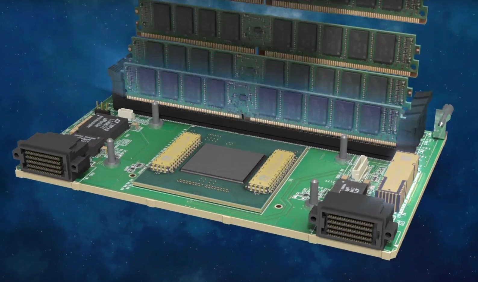
Figure 6: The Vicor MCD pre-regulation module (right) feeds power to the XPU substrate, alongside an array of DDR4 memory, on each card in the ExaScaler machine
Each processor has 2048 discrete cores, with 1GHz clocks and with on-chip, three-layer cache memory; the IC is packaged into a module with its own DDR4 high-bandwidth memory (Figure 6), for a module power demand of 130W. A total of 32 modules sit on a frame, making a brick, and eight bricks fill a tank. This means that over 33kW at 48V is required for each tank. A total of 26 tanks make up the complete machine.
The FPA implemented through PoP ensures that the highest possible proportion of the heat generated by the supercomputer is accounted for by the processing itself, and as little as possible by losses along the power chain.
Visit Vicor at PCIM 2018
Hall 9 – 443