


This article originally appeared in the May’25 magazine issue of Electronic Specifier Design – see ES’s Magazine Archives for more featured publications.
By Jackson Wightman, Applications Engineer, Voltage References and Supervisors, TI; and Kristen Mogensen, Systems Engineer, Robotics Systems, TI
Introduction
As employees in factories work alongside increasingly numerous and powerful automated robots, safety must be ensured under all circumstances to enable true collaboration between humans and robots. Appropriately powering off or making operating adjustments in the event of a failure is a primary element of safety. Thus, safe power design for these robots or other electronics is essential to comply with system-level functional safety requirements.
Safety considerations and potential failures in power supply designs
In a perfect world, a power supply will provide a constant voltage and current that never exceeds the specific design requirements. In the real world, however, not only do power supplies introduce error, but they can also occasionally fail. Table 1 includes some examples of power-supply failures and their causes.
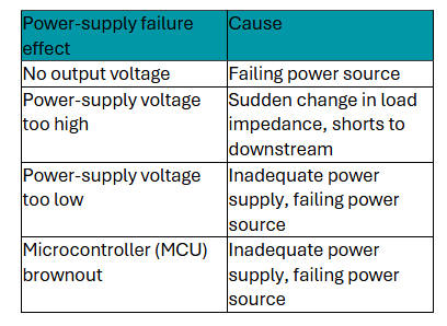
Table 1. Power supply failures and their causes
When designing devices and technologies that regularly operate around humans, you must take appropriate steps to mitigate the hazards of power-supply failures. This includes industrial mobile robots, collaborative robots or any other technology where failures could be catastrophic.
But how do you detect that a power supply has drifted out of its specifications? At what point do power supply changes become a problem? And how is a potential fault communicated throughout the entire system for industrial applications?
Introduction to functional safety and standards in industrial systems
Functional safety standards help determine whether or not a system is safe. The most popular standards include IEC 61508 and ISO 13849. Both standards look at the failure mode diagnostic coverage or safe failure fraction as well as the hardware fault tolerance to determine the system’s safety integrity level (SIL) or performance level (PL) (see Table 2).

Table 2. IEC 61508 vs. ISO 13849 safety standards
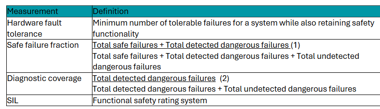
Table 3. Important functional safety rating terms
Obviously, there are multiple ways to obtain compliance with IEC 61508 SIL or ISO 13849 PL. In particular, monitoring the voltage of a power supply can increase diagnostic coverage and hardware fault tolerance alike.
Apart from the number of possible failures, the likelihood of failures is also important. In addition, you can move up in SIL or PL without changing your hardware fault tolerance by increasing your diagnostic coverage or safe failure fraction, and vice versa. Overall, voltage monitoring is an essential aspect of determining the diagnostic coverage or safe failure fraction of your system and reducing the residual FIT of the system solution.
Voltage monitoring using voltage supervisor ICs
With accurate voltage supervision, you’ll know when to completely shut off a system, reset an MCU, or make another system-level choice to achieve the safe state. There are ways to design a voltage monitoring circuit using discrete components, but in a system focused on functional safety it becomes much easier to determine the diagnostic coverage if the voltage monitoring functionality is integrated into a single subsystem circuit. This is why voltage supervisor ICs are particularly helpful for functional safety: they include different combinations of threshold accuracy, quiescent current, reset time delay, latching capability, voltage hysteresis, output type and BIST. Table 4 lists some parameters and features of voltage supervisors.
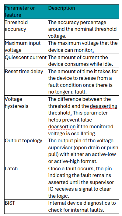
Table 4. Important voltage supervisor parameters
Once the voltage enters an undervoltage or overvoltage state, the voltage supervisor IC can notify an MCU, flip a power switch or drive a gate. Supervisors that monitor both undervoltage and overvoltage are also known as window supervisors.
When designing a safety circuit, it is important to consider the level of diagnostic coverage. Additionally, using a voltage supervisor IC can decrease the component count, allowing for a simpler design.

Table 5. How voltage monitoring affects diagnostic coverage
How voltage supervision affects functional safety ratings
When designing for a target SIL or PL, it is important to consider the hardware fault tolerance or safe failure fraction, which refers to the redundancy of your design as well as how you’ve implemented voltage monitoring into your system. The two most common standards define different ways to establish or increase the functional safety rating. Voltage monitoring is an essential part of making this determination or increasing functional safety (see Figure 1 and 2).
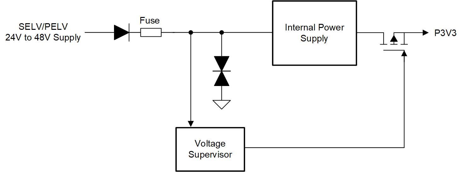
Figure 1. IEC 61800-5-2 implementation of a high-side safe power supply showing power supply and voltage monitoring

Figure 2. Another option for the IEC 61800-5-2 implementation would be a low-side safe power supply showing power supply and voltage monitoring
In Figure 2, the voltage supervisor serves a single channel, and its output can be used to disconnect a power supply working outside its safe range of operation, or to notify the MCU of a fault condition. The circuits in Figures 1 and 2 have a hardware fault tolerance of 0 and can provide a safe failure fraction or diagnostic coverage of up to 90%. Thus, the circuit in Figure 1 can provide up to SIL 2 or PL. Figure 3 shows how to increase a circuit’s hardware fault tolerance while using voltage monitoring.
Figure 3. Block diagram of an SIL 3-capable power supply using voltage monitoring
Using two voltage supervisors in parallel provides two monitoring channels. As both monitors use their own method of disconnecting the power rail, if one fails, the other will still be able to correctly and safely take the prescribed steps, enabling your design to achieve a rating as high as SIL 3.
Another method of improving functional safety is using diversity in voltage supervisor implementation. If two different voltage supervisor technologies are used to monitor the same supply rail, this would reduce the probability of a common-cause failure according to IEC 61508.
For example, functional diversity could be provided by using the TPS3762 and the TPS37 from TI in parallel because they are based on different designs.
What can be done if the voltage monitoring method fails or if the components of the voltage monitoring circuitry fail? To alleviate this issue, some voltage supervisor ICs include BIST functionality (see Figure. 4).

Figure 4. Voltage monitoring using a voltage supervisor IC with BIST features
Providing diagnostic coverage of the voltage monitors themselves can increase diagnostic coverage to as much as 99%, enabling the system to reach SIL 3 or PL e when the circuits provide the appropriate hardware fault tolerance. This is the case with TI’s TPS3762.
Voltage monitoring devices are also suitable for high voltages. The TPS3762, for instance, is designed for up to 65V, enabling direct connection to power rails. On the other hand, some designs need extra low voltage (ELV) as defined in the IEC 60449-1 standard or SELV (Safety ELV) according to IEC 62368. For example, the electrical energy source level ES1 does not allow more than 60V at the output of the power supply.
With this in mind, a safe maximum voltage level is set to 60V DC (max.) for SELV power supplies. 60V DC is a very common maximum voltage for safety standards, including safety extra low voltage and protective extra low voltage. For this reason, wide input voltage devices such as the TPS3762 have a maximum input voltage that can be monitored to 65V.
Safe torque-off as an example
Motor-drive stages are used in many environments where safety is of utmost importance, including robots working alongside humans. In a motor-drive application, it is essential to take appropriate action to shut down the system in case of a potentially dangerous state. Safe torque-off circuits are an important aspect of safe motor drives. Motor drives include a power stage consisting of gate drivers and potential isolation stages. Here, a voltage supervisor IC can be used to determine the functional safety rating of the system. Figure 5 illustrates a SIL 2 or PL d rated safe torque-off system. These voltage monitoring schemes have a hardware fault tolerance of zero. Thanks to the TPS3762’s high diagnostic coverage and its BIST feature, it is possible to obtain a SIL 2 or PL d rated system.

Figure 5. SIL 2 or PL d rated safe torque-off system block diagram
Conclusion
Thanks to advanced chips like voltage supervisors, designers can safely determine if a system bears a potential safety risk and take proper countermeasures. Functional safety will become increasingly important in the coming years. Using voltage monitoring to understand and improve the functional safety of any application can result in a safer world.


