


Amar Latif caused a stir on the UK culinary scene last year after having appeared on Celebrity MasterChef. However, not only is Amar a good cook, he also runs his own travel company, is a motivational speaker, has trekked across most of South America, and is also a TV personality. Is there no end to this man’s superpowers?
Sadly, there is. Amar is 95% blind. As technology moves on and the world struggles to keep up with it, for the visually impaired the battle is even harder. Most advancements in technology require us to spend more time in front of a screen. For the visually impaired, excessive screen time remains an ‘if only’.
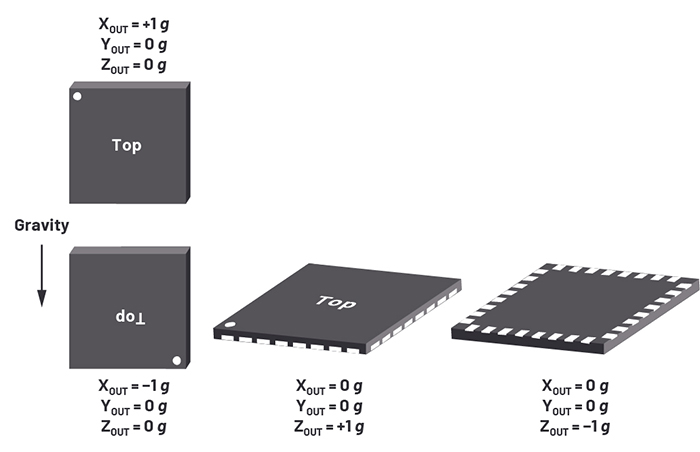
Above: Figure 1. Sensing axes of the ADXL312
If technology can be used to enrich the lives of those with a sight impairment, this can only be a good thing. With only 18% of the registered blind population being completely blind (or ‘black blind’), this leaves the vast majority with at least some sight even if they cannot distinguish detail. Thus, the idea of a spirit level for the blind was born.
Design outline
The tilt sensor design was based on the ADXL312, which is a low current accelerometer that can measure up to ±1.5g in the x, y, and z axes with the data read out via an SPI bus. The part is available in a 5 mm × 5 mm package and consumes 0.1μA in standby mode. It measures to 10-bit resolution, so the ADXL312 can detect changes as low as ±2.9mg in each axis. The ADXL312 stores the gravitational data for each axis as a two’s complement value up to ±511, which the microcontroller reads and displays on a single-line, 16-character LCD display. Figure 1 shows the sensing axes of the ADXL312.
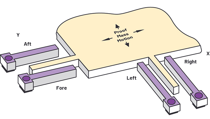
Above: Figure 2. The internal workings of the ADXL312
The part has a full-scale reading at 1.5g, so a gravitational force of 1g gives a reading two-thirds of this. Therefore, if the ADXL312 is exactly level, the z-axis register should read two-thirds full scale, while the x and y axes should read zero. Similarly, when the ADXL312 is perfectly vertical, the x-axis reading should be two-thirds full scale, while the y and z axes should read zero. If the ADXL312 starts to tilt away from any axis, the maximum reading starts to decrease while the reading on the other axes starts to increase, according to the sine of the angle of tilt.
Inside the ADXL312
The ADXL312 is a microelectromechanical system (MEMS) consisting of a polysilicon surface-micromachined structure built on top of a silicon wafer. Polysilicon springs suspend the structure over the surface of the wafer and provide a resistance against acceleration forces.
Fixed silicon fingers interleave with fingers on a moving proof mass to create differential capacitors whose characteristics can be measured. Acceleration deflects the beam and unbalances the differential capacitors, resulting in a sensor output whose amplitude is proportional to acceleration. The structure is shown in Figure 2.
The ADXL312 can be addressed using either I2C or SPI, and the x, y, and z data is stored in six internal 8-bit registers. It also has many other features including a 32-level FIFO, two multifunction interrupts, offset registers, a mechanical self-test, and auto-sleep modes.
The spirit level design
The complete circuit diagram of the tilt sensor is shown in Figure 3. The ADXL312 has a maximum supply voltage of 3.6V, while the LCD display and buzzer require 5V, so the main input to the circuit is 5V, and this is regulated down using a 3.3V, 150mA linear regulator (ADP121) to power the ADXL312, microcontroller, and E2 memory.
Port B, Pin 2 (the CAL pin) on the microcontroller is pulled high by a 10kΩ resistor. It also has a jumper enabling it to be connected to ground. On startup, the microcontroller interrogates the state of the CAL pin, and if this pin is pulled low by the jumper, it reads the x, y, and z registers, subtracts these readings from zero, then loads the result into the offset registers inside the ADXL312 as well as storing them in the external E2 memory, the 25AA040. The ADXL312 automatically adds the readings from the offset registers to any future measurement without processor interaction, thus removing the calibrated offsets.
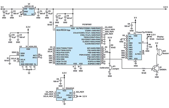
Above: Figure 3. The complete schematic of the spirit level for the visually impaired
If the jumper is removed, the CAL pin is pulled high and the calibration routine is bypassed. The offset readings are read directly from the E2 memory and loaded into the ADXL312’s offset registers. Thus, during manufacturing the spirit level can be mounted in a calibration jig with the CAL pin held low, the device can be calibrated, and the offset values stored in E2 memory. After calibration, the jumper is removed and on subsequent power-ups, the E2 memory is interrogated and the calibrated offset readings loaded into the ADXL312’s offset registers.
The software then performs eight readings of each axis, and the results are averaged and then displayed on the 16-character LCD display. The display is updated every 100ms.
Figure 4 shows that the maximum sensitivity is achieved when each sensor is close to its zero reading. This is where the slope of the sine wave is at its steepest, thus giving the maximum change in gravity reading for any change in tilt.
Luckily the spirit level only needs to measure tilt when each sensor is perfectly horizontal and the sensor reading is close to zero.
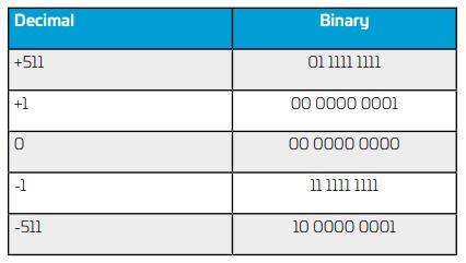
Above: Table 1. An Example of Two’s Complement Data
The software was written to enable both the x and z axes to be calibrated at once. It is easy to place the part on a horizontal platform and calibrate the x-axis of the tilt sensor. However, at this point the z-axis will be experiencing a force of 1g, so a z reading needs to be taken, compared with the full-scale count at 1g, and any error loaded into the offset register. A more accurate calibration of each axis of the tilt sensor can be achieved by calibrating in both the horizontal and vertical planes, but this requires a 2-stage calibration and a modification of the software.
Table 1 shows an example of two’s complement data. Positive numbers follow conventional binary notation. Negative numbers use the most significant bit (MSB) as a sign bit; thus, positive numbers have an MSB equal to zero, and negative numbers have an MSB equal to 1.
The two’s complement of a positive number can be found by inverting all the bits, then adding 1. Thus, the code changes from 00 0000 0000 to 11 1111 1111 when transitioning from a count of zero to a count of –1.
The software reads the x and z registers and, if the value of either register is 0 or 1023 (11 1111 1111), it sets Port B, Bit 5 high, which turns on transistor Q1 and sounds the 5V buzzer. When the tilt sensor is perfectly horizontal, the x-axis has a reading of either 0 or 1023 and when perfectly vertical, the z-axis has a reading of either 0 or 1023. Only when both registers are not equal to 0 or 1023 does the buzzer stop sounding.
Accuracy and further developments
Considering just one axis, a maximum reading of 1g is attained when gravity is acting along that axis, and this reading reduces to 0g as the part is tilted through 90° as shown in Figure 5.
Thus, the gravitational force exerted is dictated by the equation:
![]()
where Ø is the angle of tilt measured with respect to the horizontal. If the part can measure to a resolution of 2.9mg, then it can resolve to an angle of 0.17°. It is difficult to determine a figure for the accuracy of a standard bubble spirit level, since the exact position of the bubble is hard to establish. However, from experiments, the end of a 1.2m spirit level can move about 3.2mm (the width of two unpopulated PCBs) before the bubble looks off-centre. This equates to an angle of about 0.15°, indicating that we can replace a bubble spirit level with an electronic tilt sensor with little loss in resolution.
If more accuracy is required, the ADXL313 offers 11-bit resolution over a 1g scale. The interface and register sets are very similar to that of the ADXL312, so the software does not require much modification. The ADXL355 offers considerably lower noise and higher resolution.
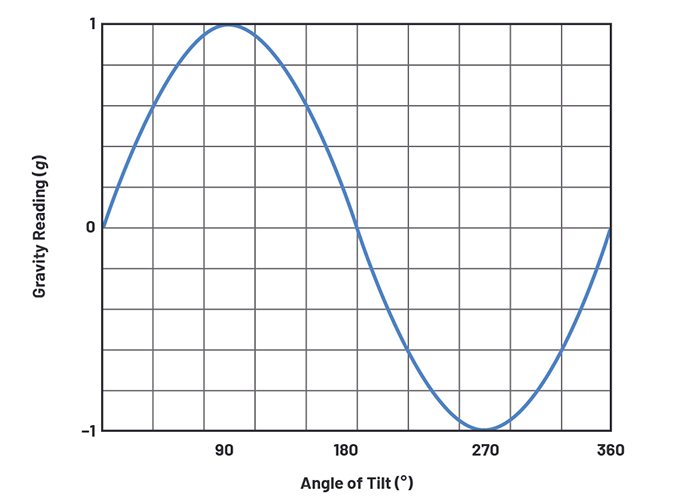
Above: Figure 4. Showing the sinusoidal change of g force with angle
The ADXL312 has a noise density of 340μg/√Hz, and the lower the bandwidth the better the noise. The part’s bandwidth is programmable (from 3.125Hz to 1,600Hz with a default set to 50Hz). Although reducing the bandwidth improves the noise, this will also reduce the update rate of the display. For this design, the bandwidth was set to 6.25Hz, which implies an rms noise of 850μg. The noise can also be reduced by taking many more readings and averaging them.
A further improvement would be to have an LCD readout showing degrees. However, this requires the use of maths functions in the C library if sines and cosines are to be included in the software. These functions occupy too much code space for a low-end microcontroller. A close approximation to a sine function can be achieved using the Taylor series expansion, and this should occupy considerably less code space.
Conclusion
The ADXL312 provides a low cost electronic tilt measurement system that is easy to interface to a low-end microcontroller. The previously described design can rival the accuracy of conventional bubble spirit levels, but with an electronic interface. This enables it to be used as a subsystem in larger designs that need to measure inclination, such as trailer levelling systems, stability control systems, and drones.
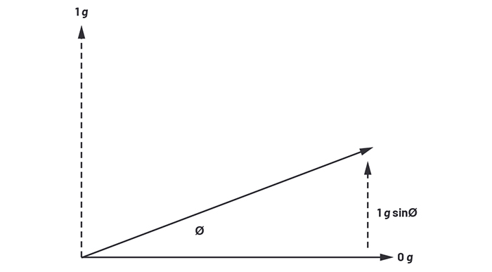
Above: Figure 5. Calculating the angle of tilt using the gravitational reading
More importantly, it can be used to increase the independence of the visually impaired, and this text shows a complete system-level design including hardware, software, and non-volatile memory, as well as an audio and visual output.