


However, full circuit protection takes much more than just a thermal fuse, and implementing protection is not a matter of finding the single best device for a given design and application. Instead, it involves first understanding which circuits need protection and then determining the best mode of protection. In general, multiple passive components are needed to provide protection, and a typical system may need a dozen or more of these specialised protection devices. Protection devices are like insurance: while the latter may only be rarely or never needed, the cost of not having it far exceeds the cost of having it.
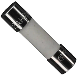
Above: Figure 1. The Littelfuse 0215.250TXP is a 250mA, 250VAC fuse in a ceramic body with a 5mm diameter and a length of 20mm. (Image source: Littelfuse, Inc.)
This article looks at where protection is needed in such medical systems, including patient-facing signal/sensor I/O, power supply, communication ports, processing core, and user interfaces. It also discusses the various types of circuit and system protection components, using devices from Littelfuse. by way of example and examines the role and application of each.
The role of protection in medical systems
For most engineers the phrase ‘circuit protection’ immediately brings to mind the classic thermal fuse, which has been in use for over 150 years. Its modern embodiment is largely due to the work of Edward V. Sundt, who in 1927 patented the first small, fast-acting protective fuse designed to prevent sensitive test meters from burning out. He then went on to found what eventually became Littelfuse.
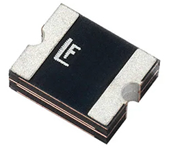
Above: Figure 2. The 2016L100/33DR 33V, 1.1 A PPTC device can be used in low voltage applications where resettable protection is needed; it reacts in under 0.5s at an overcurrent of 8A. (Image source: Littelfuse)
Since then, circuit protection options have expanded significantly in recognition of the many potential circuit failure modes. These can be:
- Internal failures that may result in a cascade of damage to other components
- Internal failures that may put the operator or patient at risk
- Internal operational issues (voltage/current/thermal) that may stress other components and lead to their premature failure
- Voltage/current transients and spikes which are an inherent and unavoidable part of the circuit’s functionality and must be carefully managed
Many of these issues apply to battery powered units, not just those that are AC line powered.
The function of many but not all protection devices is to suppress unacceptably large voltage transients. There are two major categories of transient suppressors: those that attenuate transients, thus preventing their propagation into the sensitive circuit; and those that divert transients away from sensitive loads and so limit the remaining voltage. It is critical to study device data sheets carefully for thermal and performance derating curves, as some are specified for transient protection of various durations bounded by defined voltage, current, and time limits rather than steady-state protection.
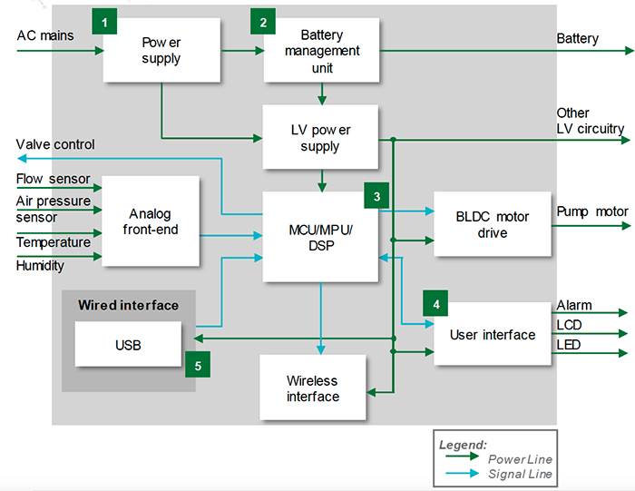
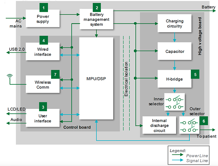
Above: Figure 3. In this ventilator block diagram, PPTC devices could be used in the battery management system as well as the USB port sections (areas 2 and 5). (Image source: Littelfuse)
Among the many electrical parameters that must be considered are clamp voltage, maximum current, breakdown voltage, reverse working maximum or reverse stand-off voltage, peak pulse current, dynamic resistance, and capacitance. It is also important to understand under what conditions each of these is defined and specified. Device size and number of channels or lines protected are also considerations. The choice of the best protection device to use in a given part of a circuit is a function of these factors, and there are often the inevitable trade-offs among the various parameters. There will almost certainly be preferred or ‘standard’ approaches, but there are also choices that must be judged, assessed, and made.
Choose wisely
There are a variety of protection options. Each has a unique functionality and set of characteristics that makes it a suitable (or only) choice for implementing protection against specific classes of faults or unavoidable circuit characteristics. The main protection options are:
- The traditional thermal fuse
- Polymeric positive temperature coefficient (PPTC) devices
- Metal oxide varistors (MOVs)
- Multi-layer varistors (MLVs)
- Transient voltage suppression (TVS) diodes
- Diode arrays
- Solid state relays (SSRs)
- Temperature indicators
- Gas discharge tubes (GDTs)
The thermal fuse is simple in concept. It uses a conducting fusible link that is fabricated of carefully selected metals with precise dimensions. The flow of current beyond the design limit causes the link to heat up and melt, thus permanently breaking the current path. For standard fuses, the time to open circuit is on the order of several hundred milliseconds to several seconds, depending on the amount of overcurrent versus rated limit. In many designs, it is a final line of protection, as it acts decisively and irrevocably.
Fuses are available for current values from under one ampere to hundreds of amperes or higher and can be designed to withstand hundreds or thousands of volts between their two terminals during fault-induced open-circuit conditions.
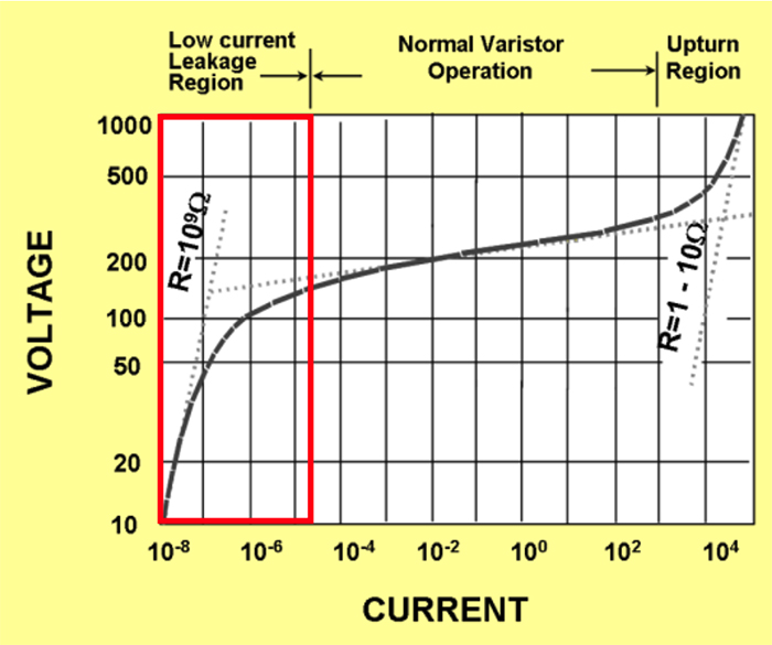
Above: Figure 4. The voltage-current (V-I) curve of the MOV shows its normal high resistance region as well as its very low impedance region, which occurs when the voltage increases beyond a design threshold. (Image source: Littelfuse)
A typical fuse is the Littelfuse 0215.250TXP, a 250 milliampere (mA), 250V AC (VAC) fuse in a 5 x 20 millimetre (mm) ceramic enclosure (Figure 1). Like most fuses, it is a cylindrical or cartridge-shaped housing that is not soldered into the circuit but instead goes into a fuse holder for ease of replacement. Fuses are also available in rectangular and ‘blade’ housings as well as those that can be soldered; note that the soldering profile must be carefully observed to avoid damaging the fuse element.
Despite their apparent simplicity, fuses have many variations, subtleties, and other factors that must be taken into account when selecting the appropriate one for a circuit. Fuses are commonly used on input AC lines, output leads where a total short-circuit may occur, or internally where any overcurrent is a serious concern such that the current flow must be fully stopped, and the problem’s source determined and fixed before operation can resume.
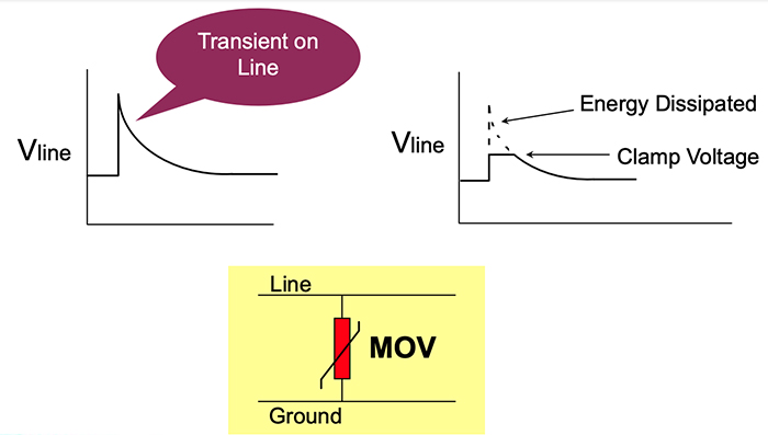
Above: Figure 5. The abrupt switch of the MOV from high impedance to low impedance when a transient voltage occurs clamps that voltage to an acceptable level. (Image source: Littelfuse)
PPTC devices serve two main types of applications: safety regulation such as for a USB port, power supply, battery, or motor control; and risk prevention for an I/O port. During abnormal conditions such as overcurrent, overload, or overtemperature, the PPTC resistance will increase dramatically, which limits the power supply current in order to protect circuit components.
Once a PPTC device trips into a high resistance state, a small amount of current continues to flow through the device. PPTC devices require a low joule heating ‘leakage’ current or external heat source in order to maintain their tripped condition. After the fault condition is removed and the power is cycled, this heat source is eliminated. The device can then return to a low resistance status and the circuit is restored to a normal operating condition. Although PPTC devices are sometimes described as ‘resettable fuses’ they are, in fact, not fuses but non-linear thermistors that limit current. Because all PPTC devices go into a high resistance state under a fault condition, normal operation can still result in hazardous voltage being present in parts of the circuit.
A good example of a PPTC is the Littelfuse 2016L100/33DR, a surface mount, 33V, 1.1 A PPTC device for low voltage (≤60V) applications where resettable protection is needed (Figure 2). It has a footprint of 4 x 5mm and will trip in under 0.5 seconds (s) at an overcurrent of 8A.
Above: Figure 6. The V07E250PL2T MOV is a through-hole leaded, 7mm disk rated for operation to 390V and can handle transients up to 1,750A. (Image source: Littelfuse)
In a typical ventilator, the 2016L100/33DR might be used to protect the battery management system’s MOSFET from high currents due to external short circuits or provide overcurrent protection for USB chipsets (Figure 3).
MOVs are voltage dependent, non-linear devices that have an electrical behaviour similar to back-to-back Zener diodes. Their symmetrical and sharp breakdown characteristics enable them to provide excellent transient suppression performance.
When a high-voltage transient occurs, the varistor impedance decreases by many orders of magnitude from a near open circuit to a highly conductive level, clamping the transient voltage to a safe level in a few milliseconds (Figure 4).
As a result of this clamping action, the potentially destructive energy of the transient pulse is absorbed by the varistor (Figure 5).
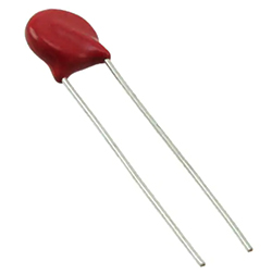
MOVs are offered in a variety of packages such as the 390V, 1.75 kiloampere (kA) V07E250PL2T, which is a small disk with through-hole leads that measures just 7mm in diameter (Figure 6). They are often used on an input AC line to prevent damage due to AC line voltage transients (area 1 in Figure 3). Note that MOVs can be connected in parallel for improved peak current and energy handling capabilities, as well as in series to provide voltage ratings higher than those normally available, or ratings between the standard offerings.

Left: Figure 7. A MLVs such as the V12MLA0805LNH can withstand repeated transient pulses without performance deterioration. (Image source: Littelfuse
MLVs are similar to MOVs and provide the same basic function but have different internal construction and thus somewhat different characteristics. MLVs are fabricated by wet stack printing layers of zinc oxide (ZnO) and metal inner electrodes, sintering, terminating, glassing, and finally plating. In general, for the same MOV voltage rating, smaller MLV parts have a higher clamp voltage at higher currents, while larger parts have a higher energy capability.
The V12MLA0805LNH MLV, for example, was tested with multiple pulses at its peak current rating (3 A, 8/20 microseconds (µs)). At the end of the test – 10,000 pulses later – the device voltage characteristics are still well within specification (Figure 7). This device should be considered for transient protection in the ventilator power supply and USB port (areas 1 and 5 in Figure 3).
TVS diodes also protect sensitive electronics from high-voltage transients and can respond to overvoltage events faster than most other types of circuit protection devices. They clamp and thus limit voltage to a certain level using a p-n junction that has a larger cross-sectional area than that of a normal diode, allowing the TVS diode to conduct large currents to ground without sustaining damage.
TVS diodes are generally used to protect against electrical overstress such as those induced by lightning strikes, inductive load switching, and electrostatic discharge (ESD) associated with transmission or data lines and electronic circuits. Their response time is on the order of nanoseconds, which is advantageous for protecting relatively sensitive I/O interfaces in medical products, telecommunication and industrial equipment, computers, and consumer electronics. They have a defined clamping relationship between the transient voltage versus voltage across, and current through the TVS, with specifics defined by the TVS model under consideration (Figure 8).
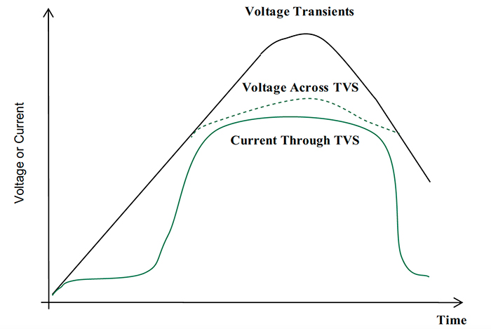
Above: Figure 8. the general relationship for a TVS between voltage transients, voltage across the TVS, and current through the TVS, with specific values determined by the selected TVS diode model. (Image source: Littelfuse)
The SMCJ33A is a unidirectional TVS diode with a 53V clamping voltage and 28A peak current rating in a 5.6 x 6.6mm SMT package; a bidirectional version (B suffix) is also available for use when both positive and negative-going transients are anticipated. In a representative application such as a portable ultrasound scanner with a high voltage pulse generator to drive the piezoelectric transducers, TVS diodes could be used to protect the USB ports as well as the LCD/LED user interface display (areas 2 and 3 in Figure 9).
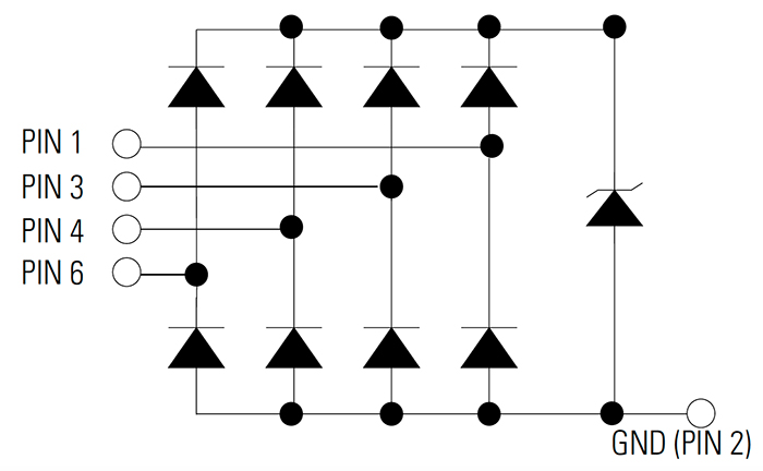
Diode arrays use steering diodes centered around a large TVS diode (such as a Zener diode) to help reduce the capacitance seen by I/O lines. These devices have a low off-state capacitance of 0.3 to 5 picofarads (pF) and are suitable for ESD levels from +/18 kilovolts (kV) to +/-30kV.
Applications include protection of USB 2.0, USB 3.0, HDMI, eSATA, and display port interfaces, to cite a few possibilities. Note that the similarly named TVS diode array provides the same basic functionality but has higher capacitance and thus is better suited for lower speed interfaces.
The SP3019-04HTG is an example of such a diode array (Figure 10). It integrates four channels of ultra-low-capacitance (0.3 pF) asymmetrical ESD protection in a six-lead SOT23 package, and also features an extremely low typical leakage current of 10 nanoamperes (nA) at 5V. As with the TVS diode, typical applications are for protection of USB ports as well as the LCD/LED user interface display (again, areas 2 and 3 in Figure 9).
SSRs, also called optoisolators, allow one voltage to switch and control an independent, unrelated voltage with near-perfect galvanic isolation (no ohmic path) between input and output. They serve multiple broad objectives. One is functional: they can eliminate ground loops between separated sub-circuits or allow the high-side drivers of a half or H-bridge MOSFET configuration to ‘float’ off ground. Another objective they serve is safety related and especially important for medical devices where their isolation provides an impassable barrier. This containment is needed where there are high internal voltages along with user or patient contact with instrumentation leads, knobs, probes, and enclosures.
The CPC1017NTR is representative of a basic single-pole, normally open (1-Form-A) SSR. It is packaged in a diminutive 4mm2, four-lead housing while providing 1,500V RMS (VRMS) isolation between input and output. It’s extremely efficient, requiring just 1mA of LED current to operate, can switch 100mA/60V, and provides arc-free switching without the need for external snubbing circuits. Further, it does not generate EMI/RFI and is immune to external radiated electromagnetic fields – characteristics that are required in some medical instrumentation and systems. In an application such as a defibrillator, designers can use it to electrically separate the low-voltage circuitry from the high voltages of the bridge driving the unit’s paddles (Figure 11).

Above: Figure 9. In this portable ultrasound scanner block diagram, a TVS diode such as the SMCJ33A with a 53v clamping voltage can be used for protection against transients at USB ports as well as at the LCD/LED display (areas 2 and 3). (Image source: Littelfuse)
Temperature indicators are specialised versions of temperature sensors such as thermistors. Although it may seem obvious that potentially hot areas such as power supplies or higher voltage sources need to be monitored for excess heating, even an I/O port such as USB-Type C can be handling significant current and thus overheat. This may be due to an internal failure or even a faulty load or shorted cable being plugged into it.
To manage this potential problem, a device such as the SETP0805-100-SE setP positive temperature coefficient (PTC) temperature indicator helps protect USB Type-C plugs from overheating. It has been designed to accommodate the unique specifications of this USB standard and is capable of helping to protect even the highest levels of USB Type-C power delivery. Available in an 0805 (2.0 x 1.2 mm) package, it protects systems consuming 100W or higher, providing sensitive and reliable temperature indication as its resistance increases from a nominal 12 ohms (Ω) at 25°C to 35 kilohms (kΩ) at 100â°C (typical values).
Above: Figure 10. A diode array such as the SP3019-04HTG provides ESD protection for multiple high-speed I/O lines. (Image source: Littelfuse
GDTs may conjure up images in engineers’ minds of large, bulky tubes with visible sparks, but they are in reality very different. These tubes are placed between a line or conductor to be protected – usually an AC power line or other ‘exposed ’ conductor and system ground – to provide a near-ideal mechanism for diverting higher overvoltages to ground.
Under normal operating conditions, the gas inside the device acts like an insulator and the GDT does not conduct current. When an overvoltage condition (called the sparkover voltage) occurs, gas inside the tube breaks down and conducts current. When the overvoltage condition exceeds the parameters of the sparkover voltage rating, the GDT turns on and discharges, diverting the damaging energy. GDTs are available as two-pole devices for ungrounded lines and three-pole devices for grounded lines, both in small SMT packages for ease of design-in and board assembly (Figure 12).
GDTs are available for sparkover values rated as low as 75V and can handle hundreds and even thousands of amperes. For example, the GTCS23-750M-R01-2 is a two-pole GDT with a 75V sparkover and a 1 kA current rating, housed in an SMT package measuring 4.5mm long and 3mm in diameter, allowing it to be placed almost anywhere to provide protection (Figure 13).
Standards guide the design
Medical devices must meet multiple safety standards, some of which apply to all consumer and commercial products, and some of which are for medical devices only. Many of these standards are international in scope. Among the many standards and regulatory mandates are:
IEC 60601-1-2, ‘Medical electrical equipment – Part 1-2: General requirements for basic safety and essential performance – Collateral Standard: Electromagnetic disturbances – Requirements and tests.’
IEC 60601-1-11, ‘Medical Electrical Equipment Part 1-11: General requirements for basic safety and essential performance – Collateral standard: Requirements for medical electrical equipment and medical electrical systems used in the home healthcare environment.’
IEC 62311-2, ‘Assessment of electronic and electrical equipment related to human exposure restrictions for electromagnetic fields (0Hz to 300GHz).’
Above: Figure 11. In a defibrillator, the SSR allows the low voltage electronics to drive the high voltage paddles while allowing the ‘floating’ upper-side drivers of the H-bridge arrangement to remain isolated from system ground (area 5). (Image source: Littelfuse)
IEC 62133-2, ‘Secondary cells and batteries containing alkaline or other non-acid electrolytes – Safety requirements for portable sealed secondary lithium cells, and for batteries made from them, for use in portable applications – Part 2: Lithium systems.’
Being careful about circuit protection device selection and how they are used goes a long way toward meeting these safety mandates. Using accepted, approved techniques and components can also speed up the approval process.
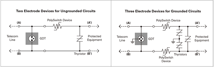
Above: Figure 12. GDTs are offered as (left) two-pole devices for ungrounded circuits and (right) as three-pole devices for grounded circuits (the GDT symbol is the ‘Z-like’ graphic to the right of each schematic diagram). (Image source: Littelfuse)
Conclusion
The requirements of where, why, what, and how to use circuit protection devices in general, and in medical units in particular, is a complicated design challenge. There are many suitable protection components, some specific to a given circuit function and others with more general applicability. Each component brings a set of attributes that makes it a best fit – or at least a better one – in the different circuit and system locations requiring such protection. No single device will fit the multiple diverse system requirements and so designers will end up using multiple protection approaches.
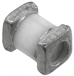
Above: Figure 13. GDTs do not have to look like the big spark-gap devices seen in movies; the GTCS23-750M-R01-2 is a 75V, 1 kA GDT in an SMT package that measures just 4.5mm in length and 3mm in diameter. (Image source: Littelfuse)
In most cases, the many decisions regarding which devices to use and how best to do so are inherently complicated and also subject to regulatory review. Designers should strongly consider asking for help from knowledgeable application engineers at the protection device vendor or their designated supplier (distributor). Their experience and expertise can reduce time to market, ensure a more thorough design, and ease the path to regulatory approval.