


There is also a trend toward more automation to monitor patients and help perform diagnosis and communications technologies such Bluetooth, Wi-Fi, and other wireless computer links, meaning technologies must co-exist the same space. For example, devices operating under FCC Part 15 rules must accept any interference from primary users of the frequency band. (Note: FCC Part 15 is applicable to certain types of low-power, non-licensed radio transmitters and certain types of electronic equipment that emit RF energy unintentionally).
These advances may bring unforeseen problems such as the interactions between the products emitting electromagnetic energy and other sensitive medical devices (intersystem interference). Even the medical devices themselves can emit EM energy which can react with themselves (intrasystem interference).
Electromagnetic compatibility (EMC), means that a device is compatible with its electromagnetic environment including itself (i.e., no interference is caused) and it does not emit levels of electromagnetic energy that cause electromagnetic interference (EMI) in other devices in the vicinity. A medical device can be vulnerable to EMI if the levels of electromagnetic energy in its environment exceed the electromagnetic immunity of itself or any nearby device. The different forms of electromagnetic energy that can cause EMI are conducted, radiated, and electrostatic discharge (ESD). The USA Food and Drug Administration (FDA) and European Safety Agencies are concerned with the need to assure EMC between devices, both medical and non-medical. An equipment manufacturer can design and test for emissions and immunity, but does not have any control over the environment in which the product will be used. This is why manufacturers must design the device with adequate protection against possible interfering emissions and immunity.
Requirements
The consequence of EMI with medical devices may be only a transient ‘blip’ on a monitor, or it could be as serious as preventing an alarm from sounding or inappropriate device movement leading to patient injury or death. While the numbers of reports with possible links to EMI have been steady, these numbers are generally not indicative of the actual occurrence of incidents. Indeed, in investigating possible EMI-related problems it is usually the case that the electromagnetic energy which caused the issue may have simply been shut off or removed from the area. Only through careful measurement and testing can the true nature of EMI be determined.
The Center for Devices and Radiological Health (CDRH) has regulatory authority over medical devices and has been the leader in the USA of examining medical device EMI (electromagnetic interference). Extensive laboratory testing has revealed that many devices can have immunity problems caused by EMI. The primary standard required by the CDRH/FDA in the US is IEC 60601-1-2: International Electrotechnical Commission – Medical Electrical Equipment – Part 1-2: General Requirements for Safety – Collateral standard: Electromagnetic Compatibility – Requirements and Tests.
Emissions can be divided into conducted emissions and radiated emissions. The primary immunity threats are radiated immunity, power disturbances and ESD. Emissions need to be controlled so that the energy generated by the device does not cause a problem to any nearby equipment. Radiated immunity deals not only from its own emissions, but more to intentionally transmitted electromagnetic energy due to RF from commercial, broadcast, and military or aircraft communications. Power disturbances can be continuous or transitory in nature caused by nearby ‘noisy’ equipment. ESD is due to a gradual build-up of charges, but creates an issue when the charge build-up reaches amplitude sufficient to create a discharge generating a conductive current surge and localised radiated transient field. It should be remembered that EMC includes self-compatibility, meaning equipment should not generate a powerful enough field to interfere with its own operation.
Unfortunately, EMC is typically the last step in a design. When all the other product features have been implemented and the functionality is established, any EMC problems are then solved. At this point, EMC compliance becomes expensive, time-consuming and difficult to handle. Manufacturers should therefore always start thinking about EMC in the early stages of product design. This pertains to the EMI power input filter as well. Designers often forget that an EMI filter can assist not only with conducted emissions, but also in meeting immunity and fast transients requirements along with radiated emissions too. A power line or mains EMI filter placed at the power entry point of the equipment is installed in to prevent EM noise from exiting or entering the equipment. Even for military-aerospace equipment, they must be protected from failure due to EMI noise, and security requirements may call for filters to protect classified data.
The design parameters for selecting an appropriate EMI filter include the attenuation or insertion loss, rated current, rated voltage, and regulatory approval requirements specified by the user. However, there are many other parameters that should be or must be considered to get the most efficiency, reliability, and proper operation from the filter.
Filter parameters
Filters are typically characterised by their insertion loss, which is expressed in dB. The insertion loss is a measure of the load reduction at the given frequency due to the insertion of the filter. It is important to note that the insertion loss of a filter is dependent on the source and load impedances, and thus cannot be stated independently of the terminal load/source impedances. Despite this fact, filter manufacturers often list an insertion loss value on a filter’s data sheet without specifying these impedance values. A common mistake is to use a filter solely based upon the standard 50Ohm input/50Ohm output insertion loss that is typically published by the filter manufacturer’s catalogue data per MIL-STD-220. This can be misleading, because for that particular filter to work properly with a device, the input impedance into the power cord of the device must be 50Ω. This is a rather unrealistic design constraint to place on a product, as it is unlikely that the use of such a filter in a product will result in the filtering results specified by the manufacturer’s insertion loss data. This is why the selected filter must still be tested in the system to verify results.
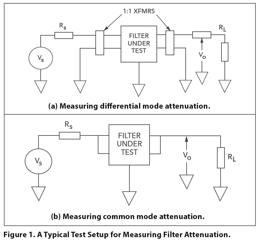
Filters should not be expected to provide voltage regulation, clamping or smoothing. The value of inductive reactance should be kept small to prevent excessive distortion of the power frequency. The maximum value of line-to-line capacitance (differential mode) reactance should be no less than 100 times the filtered device’s input impedance. These two simple rules will help avoid power frequency issues such as voltage drop or waveform distortion. Test the filter for both common mode and differential mode attenuation. Adequate differential mode and common mode filtering must fit the potential problem (see Figure 1). As any filter schematic is only an approximation of the filter circuit especially at higher frequencies, in real life the filter components exhibit tolerance, saturation, and parasitics as well as coupling.
To design a good filter, the passband must be defined just as the potential interference frequencies. The level of anticipated interference should be approximated. Comparing this to the required EMC standard will yield the degree of necessary insertion loss or attenuation.
Unless the design engineer has experience in filter designing, it is recommended that such assistance be called upon from a potential filter manufacturer like Schaffner EMC.mEMI test laboratories can also provide many filter choices.
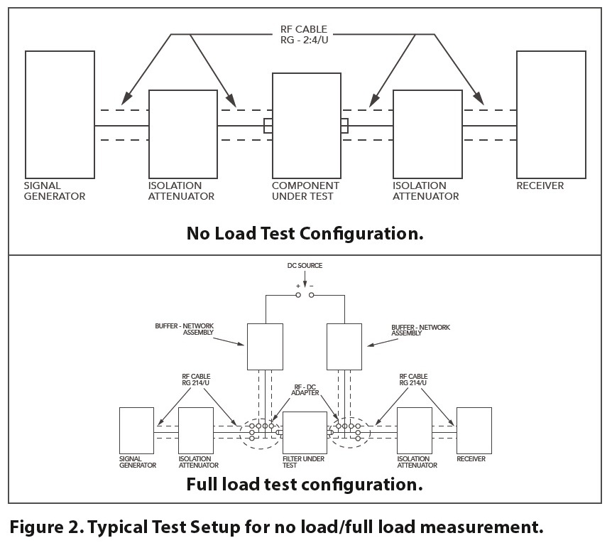
The filter’s insertion loss or attenuation characteristics should be verified not just at the no-load, but for the full-load current levels as well (see Figure 2). Since inductors are one of the key components in the filter, it is important to note that variables such as the type of core material and saturation current level through the inductor can affect the value of the choke. Using the smallest loss value possible and keeping the inductor ESR small will help. For more information, see the period, insulation resistance and voltage drop (Figures 3 and 4) must be repeated.
Current values
The rated current should be equal to the maximum input current to be drawn from the device being filtered. Chokes consist of an electrical conductor wound around a material with magnetic characteristics, the core. The choke always makes use of its magnetic characteristics to suppress RF noise. The core material determines the performance of a choke. It enhances the magnetic effects in the choke, improves the suppression characteristics and leads to more compact components. Core materials are also dependent on outside factors such as temperature or current. When used outside of its specified current range, a choke can saturate, leaving it unable to supply its original impedance (see Figure 5).
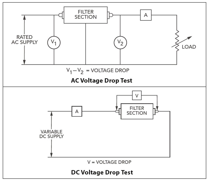 Figure 3 Typical Voltage Drop Test Configuration
The current overload characteristic of a filter demonstrates the filter’s ability to withstand the heat dissipated by the filter’s components when subjected to a higher than rated current of the filter. Typically, it is performed per paragraph 4.6.10 of MIL-F-15733 at 140% of the rated current under rated frequency for 15 minutes. After the required timeperiod, insulation resistance and voltage drop must be repeated
When the power is turned on, current begins to flow, and the initial current flow reaches a peak current value that is larger than the steady-state current value. Following this, the current value gradually decreases until it stabilises at the steady-state current. The part during which a large current flows before reaching the steady-state current is the inrush current. If the size of the inrush current exceeds that allowed by the part in use, depending on the magnitude of the inrush current (difference between the peak current value and the steady-state current value) and length of its duration (the length of time until the peak current value converges with the steady-state current value, or the pulse width), the part used in the circuit may overheat, potentially causing the electrical device to malfunction or break down.
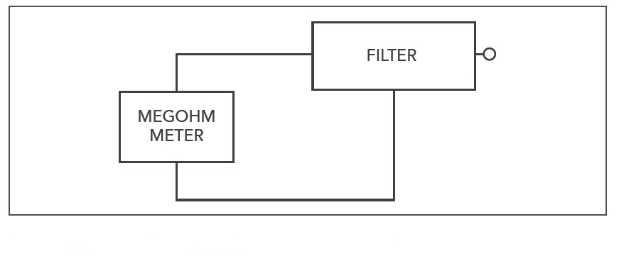 Figure 4 Setup for Insulation Resistance Test
During normal operation of electrical equipment, some current flows to earth. Such leakage currents pose a potential safety risk to the user and are therefore limited by most current product safety standards. Examples of these standards are EN 60950-1 for information technology equipment, IEC60601 for medical equipment or UL 1283 for passive EMI filters. The standards include limits for the maximum allowed leakage current. The typical leakage current values for a Class I device (protective earth) are 300μA in a patient-care area and 500μA outside that area. For a Class II device (double insulated), the values are 150μA in a patient-care area and 250μA outside that area. For passive EMI filters it is common to calculate the leakage currents based on the capacitor values against earth and other parasitic components. This leakage current is limited by the international safety agencies to prevent a danger to personal safety.
The rated frequency of the AC mains supply is either 50 or 60Hz. The operating frequency of the filter is determined by the behaviour of the capacitors. Depending on the voltage/frequency characteristic of the capacitor, it might be possible to operate a filter at a higher frequency but with a reduced input voltage.
The rating voltage should be equal to or greater than the maximum input voltage to be supplied to the device being filtered. The rated voltage of the filter defines the maximum continuous operating voltage, i.e., the maximum voltage at which the filter should be used continuously. Short over-voltages are permitted in accordance with IEC 60939, but to avoid damage to the filter capacitors, the continuous voltage should not exceed the rated voltage for an extended period of time.
 Figure 5 Saturation of a Typical Choke Due to Current
The impedance of the filter is measured at the relevant power network frequency, i.e., 50Hz for European applications and 60Hz for North American applications. This is performed at a defined temperature, such as 25°C. Current flowing through this impedance, of course, will cause a voltage drop across the filter resulting in a change in the voltage seen at the load end of the filter.
Voltage over-shoots and voltage peaks can come with high dv/dt values but are also a problem on their own. The inductance of the filter acts like a choke according to the energy storage principle. If chokes are subject to voltage pulses, voltage peaks occur every time switching on or off takes place. The higher the energy content (inductance) of the choke, the higher these voltage peaks become. These amplitudes can, in turn, reach values that cause a stress situation in the winding insulation.
Dielectric testing
Dielectric testing, sometimes referred to as hi-pot testing, demonstrates the ability of the filter capacitors to ensure higher than rated voltage. In filters, components are used that are connected between the phases of the supply network or between one phase and earth. It is therefore important to determine how well filters resist high voltages.
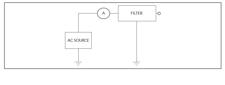 Figure 6 Leakage Current Test Circuit
A dielectric withstand test is performed by applying a voltage between enclosure and phase or between two connectors for a defined time. The current flowing between the same points is measured. Current flow means that the insulation is broken and the equipment fails the test.
During approval procedures, the test is usually performed over a longer period (typically one minute) with a defined voltage.
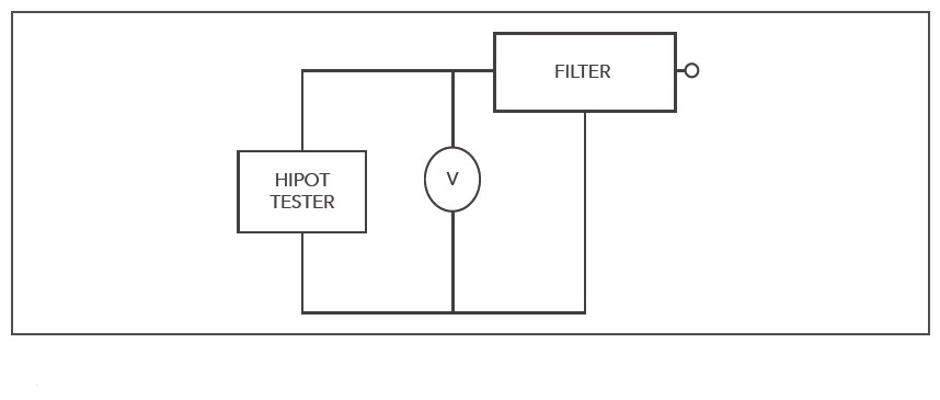 Figure 7 Typical Test Setup for Dielectric Withstand or Hi-Pot
Many safety standards require the testing to be performed on 100% of all units, but to save time, a test with higher voltage but reduced time is accepted. It should be noted that repeated high-voltage testing can lead to a damage of the insulation. This test is a high-stress test for the capacitors inside the filter. Each additional test stresses the capacitors again and leads to a reduction of lifetime. Keeping the number of tests to a minimum is advised and Schaffner recommends keeping the number of tests to a minimum and never testing the filters at higher than the indicated voltages
Insulation resistance indicates quality of the filter capacitor construction and filter insulation system. Low insulation resistance may indicate a condition which may lead to possible deterioration over time. Sometimes this can be calculated from measurements of the DC leakage current at the specified voltage.
As well as off the shelf EMC filters, there is support for manufacturers with EMC layout and custom made solutions to help manufacturers meet any EMC, mechanical or electrical challenge.
