


Now, for most indoor and outdoor new designs, as well as existing upgrades, LEDs are given first consideration. Still, designers need to be careful. Along with rapid innovation come pitfalls such as non-standard connections and mismatched end-user solutions, all contributing to a negative customer experience.
It is not just the light source itself that is radically changing. For example, LED-based lighting is also changing the design and form factor of the connectors – a necessary part of any lighting system – as well as its fixtures (called luminaires). These connectors do not carry AC line voltage; instead, they carry lower voltage DC at currents typically in the 3A to 7A range. Further, an LED-based lighting system is often part of a control network supporting the Digital Addressable Lighting Interface (DALI) and Zhaga industry standards, yielding smart, energy saving, high-performance lighting as part of an intelligent home or office.
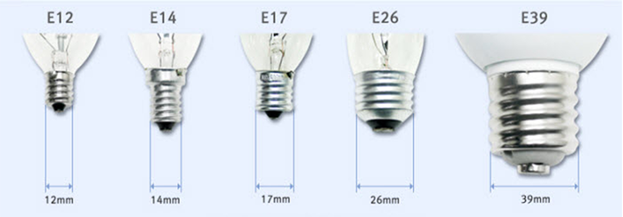
Above: Figure 1. The 26mm E26 Edison base is the most widely used lamp bulb base by far, though there are some smaller and larger ones to meet various application requirements. (Image source: LOHAS LED)
As a result, before proceeding with an LED-based lighting system design, it’s incumbent upon engineers to become familiar with the standards and how they’re reflected in real-world connectors as new designs are emerging rapidly.
This article briefly reviews why LEDs have become so pervasive, and then introduces and describes the two connection standards that ensure interoperability, rapid development, and easy deployment of smart LED-based designs. Connectors from Amphenol ICC are introduced, and their use is outlined as real-world embodiments of the relevant standards and their application.
Why LEDs are so pervasive
The growth of LEDs as a lighting source is due to many factors:
- Lower costs driving higher volumes, which in turn drives even lower costs and ever higher volumes.
- Enhancements in the basic reliability and longevity of LEDs as light sources.
- Improvements in the circuitry; primarily the power supplies that drive these LEDs.
- Improved ease of control of LEDs via smart controls and even networked I/O.
- Improvements in the quality of optical output as characterised by colour temperature (Kelvin) and colour rendering index (CRI).
- Government incentives, standards, and mandates for higher efficiency lighting to save energy (estimates are that between 15% and 20% of total energy use is for lighting).
- Development of industry and government standards that ensure both interoperability among LED-based light sources as well as compatibility with smart controllers.
The last point is especially important. One of the vital attributes of the traditional incandescent bulb, which is being displaced by LEDs and fluorescent bulbs to a lesser extent, is the near-universal use of the ‘E26’ 26mm diameter screw-in Edison-base bulb in residential settings in the US and many other countries (Figure 1). There are other sizes such as the E12 candelabra, but the E26 is by far the most widely used.
Standardisation with a single base and socket lowers costs, of course. It also encourages availability of many bulb shapes, power levels, and other attributes built around that base while reducing concerns about long-term replacement for burned-out bulbs. Early generations of LED bulbs used the E26 base for compatibility with existing sockets to get users accustomed to LED lighting. These E26 LED bulbs are still widely sold, as there are countless millions of such sockets currently in use, and that will be the situation for a very long time.
However, LEDs are quite different with respect to their current, voltage (DC), and power consumption when compared to incandescent bulbs, which are typically mains powered using 120/240VAC. Also, the E26 socket often has relatively large screw terminals for its wires, which are not ideal for powering LED-based sources (Figure 2 – top). Thus, to allow LEDs to fully realise their potential from the system level down to the physical connection, new standards and types of connectors are needed.
Recognising the need for a modern lighting interface standard, the Digital Illumination Interface Alliance (DiiA) developed the DALI standard.
DALI standard redefines lighting connectivity
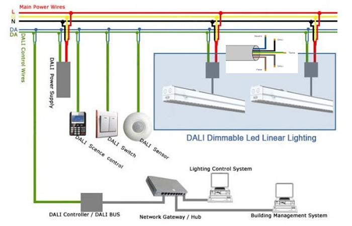
DALI is a dedicated protocol for digital lighting control that enables the easy installation of robust, scalable and flexible lighting networks (Figure 3). The first version, DALI-1, was better suited to digital control, configuration, and querying of fluorescent ballasts with little consideration for LEDs. It replaced the simple, one-way, broadcast-like operation of existing 0/1 to 10V analogue control approaches.
The standard also includes a broadcast option and, with a simple reconfiguration, each DALI device can be assigned a separate address allowing digital control of individual devices. In addition, DALI devices can also be programmed to operate in groups so the lighting systems can be reconfigured by software, thereby avoiding the need to change the wiring.
Above: Figure 3. The first version of the DALI standard defined a control base that linked all items being powered by the parallel main AC power wires. (Image source: Omnialed)
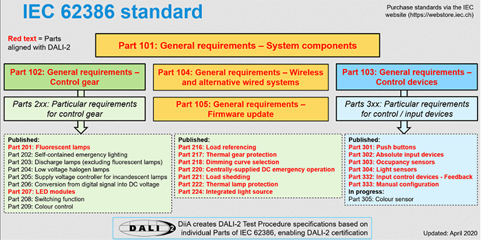
The growth of user expectations along with improvements in LED technology has encouraged the development of what is now the DALI-2 standard. DALI-2 is more than an industry standard – it is now also an International Electrotechnical Commission standard (IEC 62386). DALI-2 adds many new commands and features. While DALI-1 only included control modes, DALI-2 covers control devices such as application controllers and input devices (e.g. sensors), as well as bus power supplies. It is focused on the interoperability of products from different vendors and is supported by the DALI-2 certification programme to confirm product compatibility with the specifications (Figure 4).
As with all comprehensive standards, DALI-2 is complicated. In brief, a single pair of wires acts as the bus, and each device on a DALI network can be addressed individually. The bus is used for both signals and power and is supported by a power supply that provides up to 250mA at 16VDC (typical). The standard supports devices powered by the AC line or a DC rail.
While there are various standards that define extra-low voltage (ELV), the IEC defines an ELV device or circuit as one in which the electrical potential between electrical conductor and earth (ground) does not exceed 50VAC or 120VDC. The DALI control cable is classified as ELV potential and so requires only basic insulation from AC mains; it can be run next to those mains or within a multi-core cable that includes mains power.
Beyond DALI-2
Standards such as DALI-2 are important but can only go so far. It is not within their purview to define how the standard is to be linked to specific applications, such as LED lighting and luminaires. To address this issue, the international Zhaga Consortium has established industry specifications of interfaces for components used in LED luminaires. The consortium is a member programme of the IEEE Industry Standards and Technology Organization and has more than 120 members as of 2019.
Now’s a good time to make clear the difference between a light fixture and a luminaire. The term ‘luminaire’ is used by the Illuminating Engineering Society (IES) Lighting Handbook, ANSI/NEMA standards, and the IEC. It was added to the National Electrical Code (NEC) handbook in 2002, with a formal definition as ‘a complete lighting unit consisting of a lamp or lamps together with the parts designed to distribute the light, to position and protect the lamps, and to connect the lamps to the power supply.’ A luminaire includes the lamp and all components directly associated with the distribution, positioning, and protection of the light unit, and specifically does not include support components, such as an arm, tendon, or pole; the fasteners used to secure the luminaire; control or security devices; or power supply conductors. Luminaires take many forms and are available for a wide range of situations ranging from strictly functional outdoor street lighting to indoor office lighting, and even to ‘trendy’ retail or home lighting.
Above: Figure 4. The DALI-2 standard takes the needs of LEDs into greater consideration than DALI-1 and also adds new commands and updates. (Image source: DALI Alliance)
‘Fixture’ is not defined by the NEC and generally refers to whatever the user has in mind and may include some or all of the following elements: the lamp (bulb) – perhaps with the lamp guard – the globe, the lens or diffuser, the support, the pole or fixture fitting, and other elements.
The Zhaga specifications, which are formally called Books, address electrical, mechanical, optical, thermal, and communication interfaces, and allow the interoperability of components. By adhering to the Zhaga specifications, designers can ensure that users have components that are interoperable and can be replaced or serviced, and that an LED luminaire can be upgraded after installation when new technology becomes available.
Zhaga Book 18 and Book 20 are of special interest to designers working with LED-based luminaires; the former is focused on outdoor design while the latter is for indoor applications:
- Zhaga Book 18: ‘Smart interface between outdoor luminaires and sensing/communication modules’ specifies power and communication aspects, in addition to the mechanical fit and electrical pins for a connectivity system as defined in Edition 1.0. It simplifies the addition of application modules such as sensors and communication nodes to LED luminaires and assures plug-and-play interoperability.
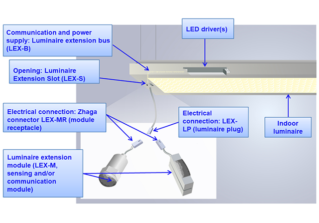
- Zhaga Book 20: ‘Smart interface between indoor luminaires and sensing/communication modules’ defines a smart interface between an indoor LED luminaire and a sensing/communication node. The node connects to the LED driver and control system, and typically can provide sensory inputs or enable communication between network components. Nodes can be installed and replaced in the field.
Connectors complete the circuit
Standards are critical, of course, and compatibility and interoperability begin with the physical interface and its connector (Figure 5). The use of the DALI specification and Zhaga standards is supported by a wide choice of connectors that meet (and exceed) their requirements while providing user flexibility for operation under different scenarios.
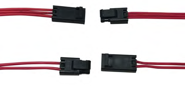
For indoor use, Zhaga Book 20 defines a separable mating interface for sensors in intelligent building networks. The Amphenol ICC FLM Series complies with the DALI standard, and enables ‘plug and play’ operability for indoor LED luminaires and sensors or communication modules. In fact, the Zhaga Consortium chose the Amphenol FLM Series as the Zhaga Book 20 standard.
Above: Figure 5. The DALI specification and Zhaga standard provide a complete cable and connector connectivity path for power and data from power source to illuminating LED in a variety of configurations. (Image source: Amphenol ICC)
Two complementary members of the Amphenol ICC FLM series illustrate the Book 20 standard in practice: the FLM-P21-00 SSL two-contact connector receptacle housing for pin-contact cable/wire to cable/wire connections, and the FLM-S21-00 two-contact SSL plug housing for socket-contact cable/wire to cable/wire. Other surface mount technology (SMT) models feature right angle and vertical configurations for design-in flexibility (Figure 6).
Among the features of this series are:
- Separable interfaces with a ‘poka yoke’ geometry (meaning ‘fool-proof’ or ‘mistake proof’), which ensures correct mating alignment.
- An available plug with tool-less poke-in termination.
- An integrated low-profile dimple-latch feature that provides five newtons minimum of retention force for secure mating, yet with easy unmating.
- A plug that is available on reel with crimp socket contacts or poke-in wire termination options to allow high-volume assembly or easy field assembly/servicing.
Of course, many intended LED applications are not as benign as ordinary indoor settings. The requirements of such applications can be satisfied with the FLH Series of wire-to-wire IP67-rated (sealed and waterproof) connectors including the FLH-P31-00 – a three-position rectangular housing receptacle with a pitch of 2.50mm – and the corresponding FLH-S31-00 rectangular housing plug (Figure 7); versions with up to six contacts are also offered.
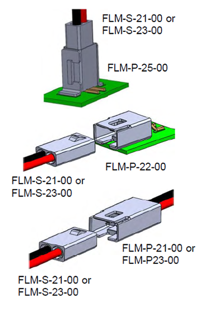
Above: Figure 6. The FLM-P21-00 receptacle housing and mating FLM-S21-00 plug housing are basic two-wire SSL connectors. (Image source: Amphenol ICC)
The sealed and waterproof performance of connectors in this series make them especially well-suited for harsh environments, and they can be used for lighting as well as HVAC, industrial, and smart home situations, while their compact design is also a benefit for space-saving applications. The contacts in these connectors are rated for a range of wire gauges and corresponding currents: 18 American Wire Gauge (AWG) for 8A; 20 AWG for 5A; down to 22 AWG for 3A.
There’s more to an installation than power connectors alone. To complete the design project, Amphenol offers other key components including the FLA-2141-30, an ANSI C136-41 compliant receptacle used to connect an outdoor luminaire in roadway, street and parking lot applications, to a photocell for dimming capabilities (Figure 8). In addition to this two-contact version, there are versions with no contacts and four contacts.
Above: Figure 7. For LEDs and other connector applications that require an IP67 rating, the FLH Series with the three-wire FLH-P31-00 rectangular housing receptacle (top left) and mating FLH-S31-00 rectangular housing plug (top right) are available, as are 2-, 3-, 4-, and 6-pin versions. (Image source: Amphenol ICC)
For more advanced sensor integration an FLB-P base can be added in place of the photocell. This allows the addition of a PC board with sensors for a variety of other functions such as motion detection, air quality, and sound detection. The complete assembly can then be protected by adding a FLB-C dome cover. Note – these are not intended for use indoors. Amphenol also offers the FLB-C70-501-001 Dome, a NEMA ANSI C136.41 translucent cover measuring 76mm in diameter and 130mm high that is designed for use with the FLB-P bases.
The FLA Series of dimming receptacles can be used with ANSI C136.10 complaint photocell or cap (open circuit or short circuit). For additional sensor integration designers need:
- The FLA receptacle
- The FLB-P base
- A PC board with sensors
- The FLB-C protective dome
Finally, the FLS-SB80-02 Luminaire Extension Module (80mm) allows lifting of the dimming assembly above the FLA Series receptacle to connect dimming and sensor modules.
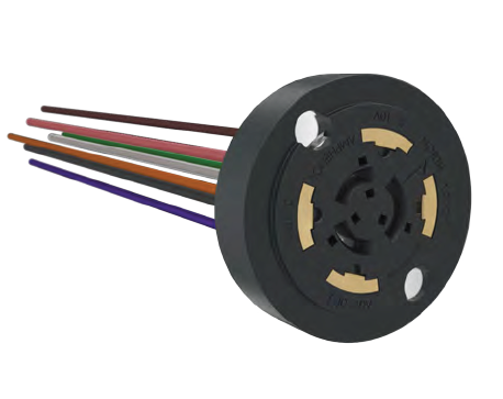
Above: Figure 8. The ANSI-compliant FLA-2141-30 dimming receptacle provides a connection between a user-supplied dimmer and the luminaire. It is intended for smart lighting that is controlled by available ambient light (shown is the four-contact variation). (Image source: Amphenol ICC)
Conclusion
LED-based lighting has dramatically transformed both indoor and outdoor illumination in industrial, commercial, and residential settings. It offers a near-perfect combination of energy efficiency, long-life, and flexibility in luminaire configurations. To simplify and accelerate LED design-in, the various families of connectors from Amphenol ICC meet indoor, outdoor, and IP67 requirements while also satisfying the Zhaga industry standards, thus enhancing system compatibility and interoperability.