


From time to time, there is a need for an isolated DC/DC solution, either for safety reasons or to ensure proper operation in a complex system. Traditional isolated solutions use either optocouplers and additional circuitry, or complex transformer designs to form a feedback loop across the isolation barrier to regulate the output voltage. The extra components make complicated and large designs.
The optocouplers degrade over time, reducing system reliability. Furthermore, end equipment form-factor is shrinking, leaving limited space for power supply, and adding thermal management challenges. The system engineer must overcome all these challenges when starting a new isolated DC/DC design. The system engineer needs a small, low-cost, highly reliable, and easy-to-design solution.
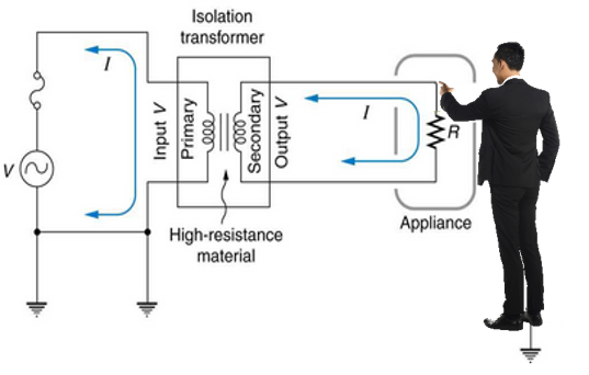
Above: Figure 1. Isolation for safety
Fortunately, there are new no-opto flyback solutions that eliminate the optocouplers, associated feedback circuitry, and the need for third transformer winding. The new solutions also provide new benchmarks for output voltage accuracy.
Where and why isolated DC/DC converters are used?
Many power systems in a variety of industries such as factory automation, building automation, e-mobility, automotive, avionics, medical, commercial, and others employ isolated DC/DC converters for one or more of the following three reasons:
Safety: To prevent current surges from damaging equipment and protect humans from the main power source. Figure 1 illustrates a power system with the main power source isolated from the secondary side, where a human operator can have physical contact with it. Without proper safety isolation, a lightning strike could send a very high voltage surge through the equipment to the operator and ground. This is mostly lethal. The isolation barrier here routes the dangerous surge energy back to the primary ground, thus avoiding it passing through the operator.
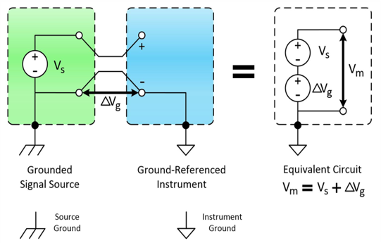
Above: Figure 2. Isolation to avoid ground loop
Avoid ground loops: In a large or complex system, grounding potential differences exist at different areas. Isolation is used here to avoid disruptive ground loops, and also isolate digital noise from the precision analogue system.
Level shifting: Occasionally, a system with a mixture of many power rails uses isolated DC/DC to generate multiple isolated positive and/or negative output voltages.
Isolated DC/DC converter basic
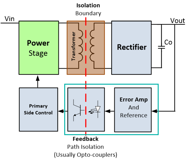
Figure 4 illustrates a traditional isolated DC/DC converter. The solution uses an optocoupler, error amplifier, and a voltage reference to form a feedback loop across the isolation barrier. In this implementation, the output voltage is sensed by an error amplifier, then compared to a voltage reference. The information is passed across the isolation barrier through an optocoupler to the primary side, where the control circuit modulates the power stage to regulate the output voltage.
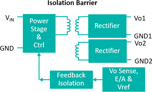
Above: Figure 3. Isolation for level shifting
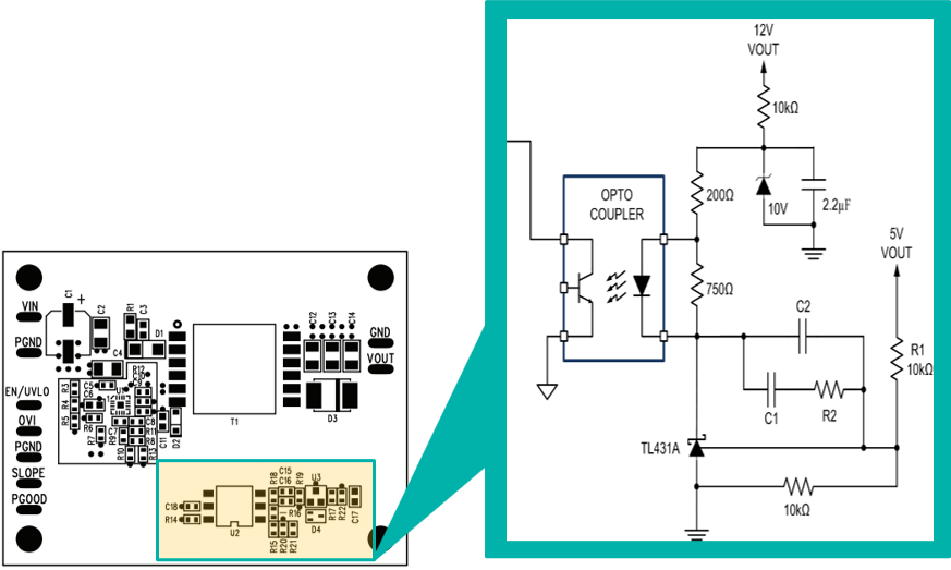
This solution serves its purpose very well until the equipment shrinks and leaves little room to fit it. The optocoupler, error amplifier, and voltage reference circuit have 12 components, which substantially add to the total design component count, and take up large board space (Figure 5). Naturally, there comes a quest to eliminate this circuitry.
The optocoupler faces another major issue: its performance varies with temperature and degrades over time, which can cause reliability issues for certain applications. Figure 6 shows a typical optocoupler’s Current Transfer Ratio (CTR) that varies 270% over the −60°C to +120°C temperature range. On top of that, this CTR drops 30% to 40% over time.
Eliminating the optocoupler
Primary side control topology: One way to eliminate the optocoupler is to employ the primary side control method. In this scheme, a third winding on the power isolation transformer is used to measure the output voltage indirectly during the OFF cycle. Figure 7 illustrates such a circuit. The reflected voltage, VW, is proportional to the output voltage following the equation:
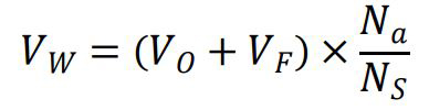
Where VO is the output voltage, VF is the output rectifier diode voltage drop, Na is the third winding number of turns, and NS is the secondary winding number of turns.
While this method effectively eliminates the optocoupler, it creates a new set of issues:
a) Adding a third winding complicates the transformer design and construction, adding more cost.
b) The reflected voltage involves the output rectifier diode voltage, VF. Also, VF varies with load and temperature. This produces sensed output voltage error.
c) The leakage inductance ringing on VW further adds to the reading error of the sensed output voltage.
Above: Figure 4. Traditional isolated DC/DC converter using optocoupler and associated feedback circuitry
This primary side control method offers poor output voltage regulation and thus is not practical in many applications, forcing the designer to use a post regulator, which adds even more cost and increases the total solution size.
No-opto flyback topology: The No-Opto Flyback DC/DC is a variation of the primary side control method. It eliminates issue (a) mentioned earlier by sensing the primary side voltage directly, thus not requiring a third winding in the power transformer. This improvement significantly reduces the complexity in the transformer design and construction, and PCB layout. Figure 8 describes this topology.
The reflected voltage, VP, is proportional to the output voltage following the equation:
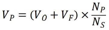
Where VO is the output voltage, VF is the output rectifier diode voltage drop, NP is the primary winding number of turns, and NS is the secondary winding number of turns.
No-opto flyback topology is not new, and it still suffers from the two remaining issues (b) and (c) mentioned earlier. In this case, (c) applies to the leakage inductance ringing on VP instead of VW. Poor output voltage regulation remains the most technical challenge for this no-opto flyback circuit.
Above: Figure 5. Traditional feedback circuit using optocoupler, error amplifier, and a voltage reference
Thankfully, recent circuit design advancement and proprietary techniques have improved this bottleneck in a big way. Let us take a closer look.
Conquering poor output voltage regulation issues: Figure 9 shows a new product from Maxim Integrated, the MAX17690, which provides a no-opto flyback isolated DC/DC converter solution with +/-5% output voltage regulation.
To combat the sensed output voltage reading error, the MAX17690 samples the reflected voltage when the secondary current, ISEC, is low. This technique alleviates the diode voltage drop variation due to output loading. The IC also has a provision to compensate for the diode voltage, and its variation due to temperature. It also uses advanced techniques to filter out leakage inductance ringing.
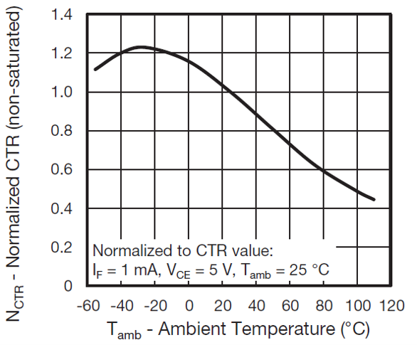
Above: Figure 6. Optocoupler collector current vs. ambient temperature
Altogether, this IC brings a new output voltage regulation benchmark to the no-opto flyback topology.
Figure 10 shows a variation, MAX17691, that also integrates the power FET and current-sensing element, thus requiring very few external components to complete a whole circuit. It truly offers a high-performance isolated DC/DC converter solution in its simplest form. Figure 11 shows MAX17690 and MAX17691’s performance over temperature, line, and load variations.
Conclusion
Shrinking equipment and board space render ineffective large, traditional isolated DC/DC converters that use optocouplers for feedback loop. The optocoupler performance varies with temperature and degrades over time. The no-opto flyback topology is simpler, requires fewer external components, and is naturally a better choice. New advancement in design techniques largely improve output voltage regulation, making the no-opto flyback DC/DC converter practical and a proper choice for isolated power supply applications.
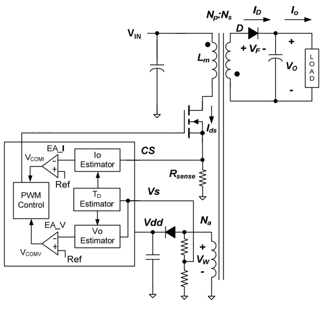
Above: Figure 7. Primary side control using third transformer winding
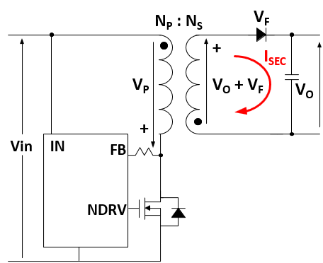
Above: Figure 8. No-opto flyback circuit
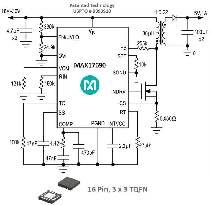
Above: Figure 9. No-opto flyback circuit achieving new output voltage regulation benchmark
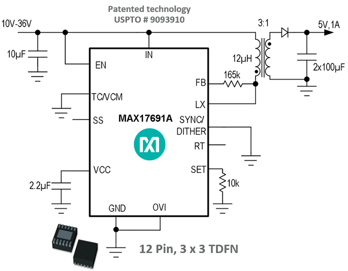
Above: Figure 10. Highly integrated no-opto flyback solution
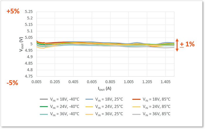
Above: Figure 11. MAX17690/91 output voltage regulation. A new benchmark