


The title of Bob Dylan’s 1964 hit ‘The Times They Are A-Changin’ certainly holds true for home appliance products. The world of consumer electronics needs to evolve and keep pace with the growing desire of their customers and play a part in enabling the dream of a truly connected world.
The internet of things (IoT) trend has finally reached our homes. It has given us remote control and access to any object from any part of the world as long as it is connected to the internet. Wireless speaker systems, thermostats, home security and monitoring systems, domestic robots, smoke/CO detectors, lighting, home energy use monitors, door locks, refrigerators, laundry machines or water detectors, nowadays come with an integrated wireless communication module supporting some form of WLAN, Zigbee, LPWAN or Bluetooth technology.
The additional connectivity features bring along new challenges and compliance requirements. Products failing to satisfy regulatory requirements may incur hefty fines and in some countries may even be subject to a sale stop enforcement. Almost all new connected products come with a display, speaker systems and apps support for easier user interaction. This gives rise to a new set of security, functionality and quality assurance challenges.
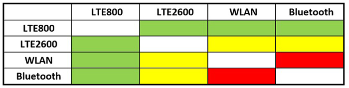
Above: Table 1. Risk assessment Matrix (green colour represents no risk, yellow is moderate risk and white and red represent extremely risky)
The connectivity technologies (WLAN, Bluetooth etc.) mostly operate on the 2.4GHz ISM band. In some cases, the frequencies overlap on one another and create performance degradation. This is what is known in the RF industry as a wireless coexistence problem. Coexistence issues degrade the user experience and since a non-technical user may not understand the source of the problem, they easily blame the product instead. This results in brand defamation.
Responsibility for testing
Most device manufacturers source wireless communication modules and antenna modules from different third party suppliers, connect the two components together, and integrate them into their products in the end. The individual component suppliers certify their products according to different regulatory norms.
The wireless module manufacturers perform in-device coexistence measurements using conducted test methods, but no radiated or over-the-air (OTA) testing with their DUT connected to an integrated antenna system takes place. So the performance of the complete system is unknown. Similarly, the antenna module suppliers certify the antenna radiation performance and other antenna relevant parameters without having any integrated wireless module from the certification test. In this case, the complete system performance is also unclear.

Above: Figure 1. Spectral positions where interference signal is introduced on the wanted band
When the device manufacturer finally connects and integrates the two individual components, a complete new product is created, which has not yet been certified. After integration, depending on mount position of the antenna and the coupling of the antenna with the body of the device, different electromagnetic interference (EMI) signals are picked up from different interference sources that come to or pass by in the vicinity of the device. Interference source of interest is any foreign device that is transmitting RF signal in the adjacent or overlapping frequency bands. Most device bodies are made of steel or aluminium, which sometimes results in the antenna coupling with the device. Consequently, the radiation pattern also changes from the one certified by the antenna module supplier.
Therefore, it is crucial that the device manufacturers test and qualify the device in its final form. This is done through radiated proximity wireless coexistence testing.
The challenges of testing connected devices
To make sure that the end product meets all the described requirements, it has to go through a complex set of tests. These include coexistence and user experience tests that guarantee high quality of service in real world use and ensure security and product compliance. These steps are needed to minimise any potential risks before introduction to the market. This process also requires the intended use case of the device under test (DUT) to be defined in order to identify the baseline electromagnetic (EM) environment and the corresponding functional performance of the wanted communication system. As a result, it is possible to define the worst case RF scenario in the lab in order to recreate it later on for testing purposes.
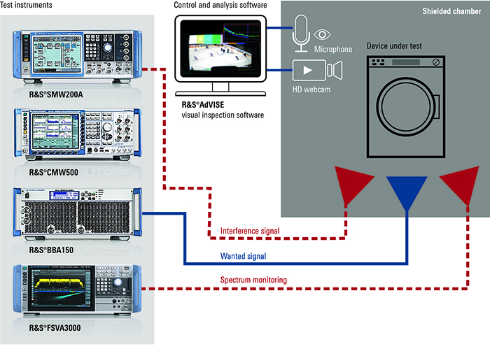
Above: Figure 2. Setup of a possible test solution
To make sure that the end product meets all the described requirements, it has to go through a complex set of tests. These include coexistence and user experience tests that guarantee high quality of service in real-world use and ensure security and product compliance. These steps are needed to minimise any potential risks before introduction to the market. This process also requires the intended use case of the device under test (DUT) to be defined in order to identify the baseline electromagnetic (EM) environment and the corresponding functional performance of the wanted communication system. As a result, it is possible to define the worst-case RF scenario in the lab in order to recreate it later on for testing purposes.
Let us consider a smart washing machine that is connected to a WLAN network as an example. According to its intended use case, the washing machine is normally located in an area where the EM environment is mostly time invariant and stable. The worst-case scenario occurs when the washing machine is located in an area with very weak WLAN signal while a smartphone running an active WiFi hotspot and Bluetooth application, transmitting at maximum power, is placed on top or next to it. What happens if an additional smartwatch is brought to this equation? The test challenge is to recreate this exact EM environment and test conditions inside an anechoic chamber in a repeatable manner.
Interference signals
The topic of interference signals is heavily debated among experts in the wireless coexistence testing industry. The target of testing the coexistence is to ensure satisfactory receiver performance of the DUT. This means that we need to find a repeatable test strategy and the correct type of interference signal for testing receivers supporting different type of wireless communication standards.
There are two approaches on how to select the correct type of electromagnetic interference (EMI) signal.
Approach 1: The first approach involves performing a complete risk assessment analysis on the DUT capability in terms of technology, frequencies and bands supported. When this is done, a risk assessment matrix will determine the interference signals and spectral position that is required for the specific DUT.
For example, let us consider a DUT supporting WLAN, Bluetooth and LTE (bands 7 and 18). WLAN and Bluetooth operate on the 2.4GHz band, LTE band 7 on the downlink operates on the 2.6GHz band, and LTE band 18 operates on the 860MHz band. Table 1 shows the risk assessment matrix for this particular DUT.
If we consider WLAN as our wanted system, then the interference sources are other Bluetooth and WLAN transmissions, since they overlap on the frequency spectrum and thus causing the probability of coexistence to be high. In case of the LTE 2.6GHz transmission, the likelihood of coexistence issues is moderately low since it does not overlap on the 2.4GHz band and would be considered as a moderate risky interference source. Finally, for WLAN, the LTE 800 band transmission is of no risk and thus not considered an interference source.
Approach 2: In this case, we test an individual standard with a common interference signal strategy. The properties of an interference signal that affects the performance and reception quality of the wanted system are EMI signal bandwidth, power level and spectral position. The modulation technique of the EMI signal does not influence the functional performance of the wanted system, but it is advised to use some kind of QPSK or QAM modulated EMI signals. As a result, the EMI signal of different bandwidth and power level can be introduced to the wanted band on the spectral positions (centre of the band, band edges) as shown in Fig. 1. These are all in-band positions since the most influence on the wanted system is seen at the in-band EMI positions. Out-of-band EMI positions are also possible, but particle experience shows that most modern receivers have decent filtering capability to filter out the out-of-band interferences.
Wanted signal
Wireless communication radios are designed to support the maximum data rate possible. If the RF environment allows, the radio will select the maximum available channel bandwidth and the maximum supported high order modulation scheme to achieve the maximum data rate. Therefore, when performing coexistence testing it is necessary to configure the wanted system with the maximum capability that the DUT supports for each standard.
A possible test and measurement solution as illustrated in Figure 2 includes a radio communication tester, a vector signal generator and an optional high power amplifier, a spectrum analyser and a real-time inspection software.
The DUT is placed in a large semi-anechoic chamber. The antenna of the radio communication tester is pointed directly towards the integrated antenna of the DUT. The radio communication tester is used to establish active end-to-end connection with the DUT by emulating a non-cellular network (such as Bluetooth and WLAN) as well as cellular networks (such as 3G, 4G networks) if required. The high power amplifier is optionally used to boast the signal level in radiated testing conditions. A baseline functional performance test is done, and the results for all the relevant physical and application layer KPIs (such as throughput data rate, PER, BLER, video and audio performance) are recorded.
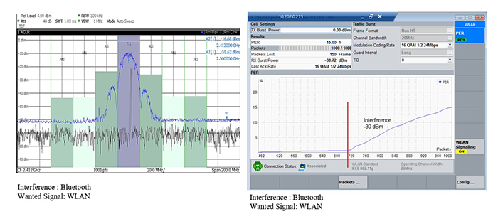
Above: Figure 3. The spectral plot of wireless coexistence and the measurement result of WLAN communication with Bluetooth in band EMI
In the next iteration, the power level of the wanted signal is reduced to the cell edge condition to replicate the worst-case scenario and the interference signal is introduced using the vector signal generator. The vector signal generator is used to generate realistic wideband modulated EM interference signals. It is an extremely powerful instrument that can generate any type of signal at any frequency on the fly. The functional performance in presence of results at this point will show the divergence from the baseline results. While performing coexistence testing, it is important to monitor the RF spectrum, which is listed as a mandatory step in most standards. This is done using the spectrum analyser. Most modern spectrum analysers can be configured to operate in both real-time spectrum analyser and a swept-tuned spectrum analyser mode. Most home automation products these days come preloaded with a display screen and a built-in loudspeaker system. These two features help the users interact with the product. Therefore, it is of immense importance that the functional performance of the application level is also tested in presence of interferences.
The DUT can stream video and audio from the streaming server of the radio communication tester over the WLAN link and inspection software will perform real-time picture and sound quality analysis. There are specialised solutions on the market such as the R&S AdVISE inspection software that uses any USB based HD webcam and microphone to collect live data in order to monitor in real-time the audio and video performance of the DUT. This enables fault events to be recorded and documented automatically on the test report.
Test results
Figure 3 shows the spectral plot of wireless coexistence scenarios of a WLAN transmission and a 1MHz wide EMI Bluetooth signal in the middle of the wanted band. The WLAN module is connected to the radio communication tester access point (AP) using the IEEE 802.11g 20MHz channel. The measurement result of WLAN communication with Bluetooth in band EMI shows an average 15% PER over a transmission of 1,000 packets over the network. The EMI signal is introduced with a power level of -30dBm.
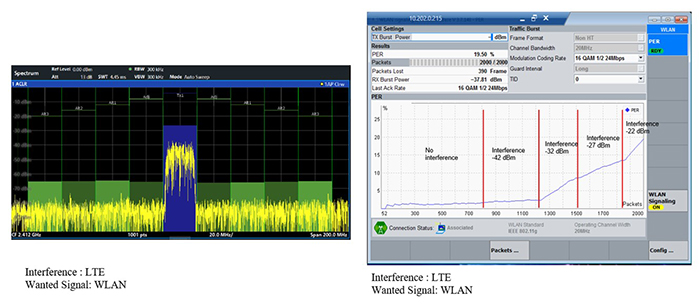
Above: Fig. 4: The spectral plot of wireless coexistence and the measurement result of WLAN communication with Bluetooth in band EMI
Figure 4 shows the spectral plot of wireless coexistence scenarios of a WLAN transmission and a 20MHz wide EMI LTE signal in the middle of the wanted band. The WLAN module is connected to the radio communication tester access point (AP) using the IEEE 802.11g 20MHz channel. The measurement result of WLAN communication with LTE in band EMI shows an average 19.5% PER over a transmission of 2,000 packets over the network. The EMI signal is introduced with a gradually increasing power level with each increment resulting in the PER increasing steeply.
An increasing need for testing
This article describes a systematic approach on how to perform radiated proximity wireless coexistence testing on a product in its final form. Proximity wireless coexistence testing is a new form of testing that is slowly picking up pace in popularity. This is because it not only helps manufacturers testing compliance but could also double as an end-of-line functionality test. Most products these days get the latest firmware update before they leave the factory. If there is a wireless coexistence issue hampering the last software update, they might fail to perform once sold to the customer. The call-back, trouble shooting and replacing of the product is very expensive. Therefore, a final test just prior to loading it onto the truck would save enormous time and resources for the manufacturer.
A modified and short open lab wireless coexistence test routine checks for functionality and real-world performance of the product in its intended environment. This gives the device manufacturer an added level of confidence in their product and helps to uphold the brand reputation.