


Electronic fuses – often written as eFuse or e-Fuse – are an excellent solution for these situations, sometimes replacing but usually supplementing the thermal fuse.
eFuses are based on a simple concept of current sensing by measuring voltage across a known resistor, and then turning off the current flow via a field-effect transistor (FET) when it exceeds a design limit. The eFuse offers features, flexibility, and functions which a thermal fuse cannot provide.
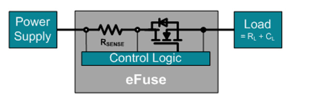
Above: Figure 1. In an eFuse, as current from supply to load passes through a sense resistor, it is monitored via the voltage across that resistor; when it exceeds a set value, the control logic turns the FET off, blocking the flow of current to the load. (Image source: Texas Instruments)
This article will describe how eFuses work. It will then explore the features, additional functionality, and effective use of these active-circuit fuses. Along the way, example solutions from Texas Instruments, Toshiba Electronic Devices and Storage, and STMicroelectronics will be introduced and their effective use outlined.
How do eFuses work?
The operating principle of a conventional thermal fuse is simple, well-known, and reliable: when the current passing through the fusible link exceeds its design value, that element heats up sufficiently to melt. This breaks the current path, and the current goes to zero. Depending upon fuse rating and type, as well as the amount of overcurrent, a thermal fuse can react and open the current path in a few hundred milliseconds to several seconds. Of course, as with all active and passive components, there are many variations, subtleties, and shadings of operation available for this entirely passive device that is simple in principle.
In contrast, electronic fuses operate on a very different principle. They provide some of the same functionality but also add new, different functions and features. The basic eFuse concept is also straightforward: the current to the load goes through a FET and a sense resistor and is monitored via the voltage across that sense resistor. When it exceeds a preset value, the control logic turns the FET off and cuts the flow of current (Figure 1). The FET, which is in series with the supply line and load, must have very low on-resistance so it does not induce excessive current-resistance (IR) drop or wasted power.
Above: Figure 2. The Texas Instruments TPS26620 eFuse is shown set to trip at a current of 500mA in this 24V DC PLC application. (Image source: Texas Instruments)
It may seem that an eFuse is simply a more complicated, active version of the classic, passive thermal fuse. While that is true, the eFuse also offers some unique attributes:
Speed: They are fast-acting devices with cut-off reaction times on the order of microseconds, with some designed to provide nanosecond response. This is important for today’s circuits with relatively sensitive ICs and passive components.
Low-current operation: Not only can eFuses be designed to work at low currents (on the order of 100mA or less), but they also work well at low, single-digit voltages. At these levels, thermal fuses often cannot be supplied with sufficient self-heating current to induce melting of their fusible link.
Resettable: Depending on the specific model, the eFuse offers the choice of remaining off after it is activated (called latch-off mode), or to resume normal operation if the current fault subsides (auto-retry mode). The latter setting is especially useful in transient inrush-current situations where there is no ‘hard’ fault, such as occurs when a board is plugged into a powered bus. It is also useful where replacement of the fuse would be difficult or costly.
Reverse current protection: An eFuse can also provide reverse current protection, which a thermal fuse cannot do. Reverse currents can occur when the voltage at the system output is higher than at its input. This can occur with a set of redundant power supplies in parallel, for example.
Overvoltage protection: With some additional circuitry, the eFuse can also provide overvoltage protection from surges or inductive kicks, turning off the FET when the input voltage exceeds the set overvoltage trip point, and remaining in the OFF condition as long as that overvoltage condition persists.
Reverse polarity protection: The eFuse can also provide reverse polarity protection, quickly cutting off the current flow if the source is reverse connected. An example is a car battery that is reverse connected for a brief moment due to accidental cable contact.
Slew rate ramping: Some advanced eFuses can also provide defined power-down/power-up current slew rate ramping by controlling the on/off transition of the pass element FET, via an external control or by using fixed components.
Above: Figure 3. The Toshiba TCKE805 18v, 5A eFuse uses a test-and-repeat cycle sequence to assess if it is safe to restore the current flow. (Image source: Toshiba)
For these reasons, eFuses are an attractive current-flow control solution. While they can be used in place of thermal fuses in some cases, the two are often paired. In such an arrangement, the eFuse is used for localised, fast-response protection for a subcircuit or PC board such as in hot-swap (hot plug) systems, automotive applications, programmable logic controllers (PLCs), and battery charge/discharge management; the complementary thermal fuse provides system-level protection against large, gross failures where a hard and permanent shut off is needed.
In this way, the designer gets the best of both worlds, with all the capabilities of eFuses plus the clear, unambiguous operation of the thermal fuse. This is achieved without technical tradeoffs or drawbacks. There are, of course, some tradeoffs as with any design decision. In this case it’s an incremental increase in real estate and a slightly larger bill of materials (BOM).
Picking an eFuse: Functions and applications
When choosing an eFuse, there are some basic parameters to consider. The top-tier consideration is, not surprisingly, the current level at which the fuse acts. This typically can range from under 1A up to about 10A, as well as the maximum voltage the fuse can withstand across its terminals. For some eFuses, this current level is fixed, while for others it can be user set via an external resistor. Other selection factors include response speed, quiescent current, size (footprint), and the number and type of external support components needed, if any. In addition, designers must consider any additional features and functions the different eFuse models may offer.
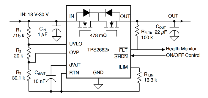
For example, PLCs are an application where eFuses are beneficial in different subcircuits that may be prone to sensor I/O and power misconnection. There are also current surges as wire connections are made or boards are hot swapped. An eFuse such as the Texas Instruments TPS26620 is often used in these 24V applications. It is shown set for a 500mA limit in Figure 2. It operates from 4.5V to 60V at up to 80mA, with a programmable current limit, overvoltage, undervoltage, and reverse polarity protections. The IC can also control inrush current and provide robust protection against reverse current and field miswiring conditions for both PLC I/O modules and sensor power supplies.
Above: Figure 4. In latch mode, unlike the auto-retry mode, the Toshiba eFuse does not reset until directed to do so via the IC’s Enable pin. (Image source: Toshiba)
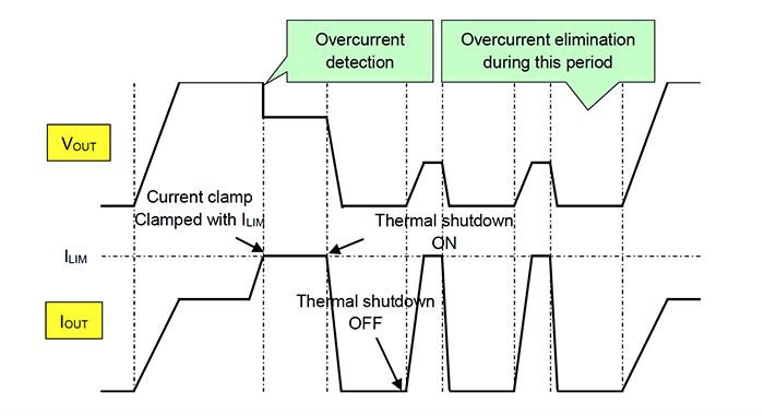
The timing diagrams in Figure 3 for Toshiba’s TCKE805, an 18V, 5A eFuse, show how one vendor has implemented the auto-retry versus latched modes. In auto-retry mode (set by the EN/UVLO package pin), the overcurrent protection function prevents damage to the eFuse and its load by suppressing power consumption in the event of a fault situation.
If the output current, set by the external resistor (RLIM), exceeds the limit current (ILIM) value due to a load error or short circuit, the output current and output voltage decrease, thereby limiting the power consumed by the IC and the load. When the output current reaches the preset limit value and overcurrent is detected, the output current is clamped so that no more current than ILIM flows. If the overcurrent situation is not resolved at this stage, this clamped condition is maintained and the eFuse temperature continues to rise.
When the eFuse temperature reaches the operating temperature of the thermal shutdown function, the eFuse MOSFET is switched off, stopping the flow of current entirely. The auto-retry operation attempts to restore the current flow by stopping the current, which lowers the temperature and releases the thermal shutdown. If the temperature rises again, the cycle repeats and stops the operation until the overcurrent situation is eliminated.
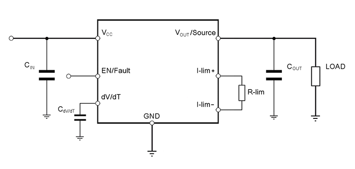
Above: Figure 5. In the conventional wiring of the STEF033AJR, the resistor which establishes the limiting value, R-lim, is placed between two designated terminals. (Image source: STMicroelectronics)
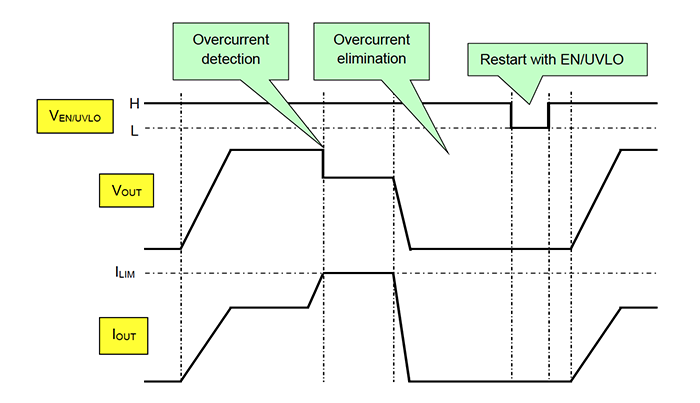
In contrast, latch mode clamps the output until the eFuse is reset via the Enable (EN/UVLO) pin of the IC (Figure 4).
Some eFuses can be configured to overcome issues associated with current sensing across a resistor, such as the associated IR drop which reduces the output-side rail voltage. For example, the 3.3V STEF033AJR from STMicroelectronics has nominal maximum current and FET on-resistance values of 3.6A and 40mΩ, respectively, for the DFN package; and 2.5A and 25mΩ for the flip-chip package.
In the conventional connection shown in Figure 5, at higher current values, even a modest IR drop of about 15mV in the supply rail through the on-resistance may be significant and worrisome.
Modifying the conventional connection by putting the resistor between the positive-side limit connection and the output voltage connection (VOUT/Source), implements a Kelvin-sensing arrangement that compensates for the IR drop (Figure 6).
Note that although eFuses are semiconductors and can work down to single-digit voltages, they are not limited to that low region. For example, eFuses in the Texas Instruments TPS2662x family are rated for operation from 4.5 to 57V.
eFuse: Make or buy?
In principle, it is possible to build a basic eFuse from discrete components using a couple of FETs, a resistor and an inductor. The earliest eFuses were built this way, with the inductor serving two purposes: filtering the DC output and also acting as a sense resistor using the DC resistance of its windings.
However, an enhanced eFuse with more consistent performance, which takes into account the characteristics of its components, as well as real-world operational considerations, requires more than a few discrete components. Even with the additional components, it can provide only basic eFuse functionality (Figure 7).
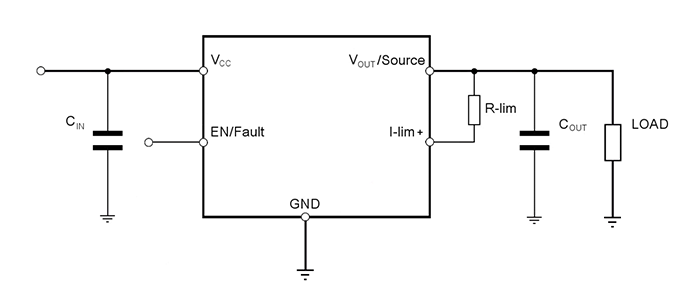
Above: Figure 6. To reduce the effects of current-sense IR drop, the negative side of the limit resistor is connected to the voltage output (VOUT/Source). (Image source: STMicroelectronics)
The reality is that the accumulation of active and passive discrete components soon gets unwieldly, is prone to unit-to-unit performance variations, and has issues related to initial tolerance, component ageing, and temperature-induced drift. In short, a DIY ‘make’ discrete solution has many limitations:
- Discrete circuits generally use a P-channel MOSFET as a pass element, which is more expensive than an N-channel MOSFET with respect to achieving the same on-resistance value (RDS(ON)).
- Discrete solutions are inefficient as they include power dissipation across a diode with a corresponding rise in board temperature.
- It is difficult for discrete circuits to include adequate thermal protection for the pass element FET. As a result, that critical enhancement must be left out, or the design must be substantially oversized to provide a suitable safe operating area (SOA).
- A comprehensive discrete circuit needs many components and considerable board space, and the need for protection circuit robustness and reliability add additional components.
- Though the output voltage slew rate in discrete designs is adjustable using resistor and capacitor (RC) components, these components must be sized with careful understanding of the gate characteristic of the pass FET.
Even if a discrete component solution was acceptable, it would be limited in its features compared to an IC solution. The latter can include some or all of the many additional functions previously cited, as seen in the Figure 8 eFuse block diagram. In addition, the IC solution is smaller, has more consistent and fully characterised performance, and offers an implementation ‘peace of mind’ that a multicomponent solution cannot offer, and does so at a lower cost. Note that the TPS26620 data sheet has several dozen performance graphs and timing diagrams covering a variety of operating conditions, all of which would be difficult to create for the discrete ‘make’ approach.
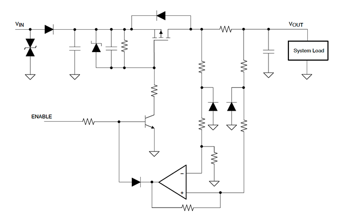
Above: Figure 7. An eFuse with basic functionality using discrete components must anticipate and overcome their inherent limitations. (Image source: Texas Instruments)
There is another critical reason to buy a standard eFuse IC rather than take the DIY discrete route: regulatory approval. Many fuses – thermal and eFuse – are used for safety-related functions to prevent conditions where excessive current can cause component overheating and possibly fire, or cause harm to users.
All conventional thermal fuses are approved by the various regulatory agencies and standards to provide a fail-safe current shutoff when used appropriately. However, it would be very difficult and time-consuming, and likely even impossible to get the same approvals for a discrete solution.
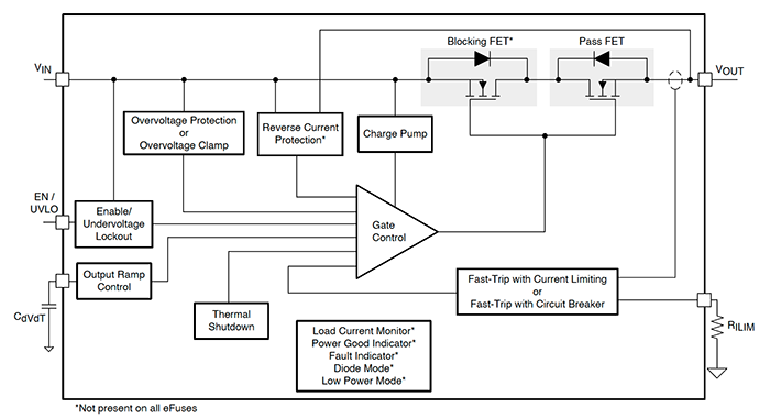
Above: Figure 8. The outward simplicity and appearance of a full-featured eFuse conceals its internal complexity, which would be very difficult to reproduce using discrete components. (Image source: Texas Instruments)
In contrast, many of the eFuse ICs are already approved. For example, eFuses in the TPS2662x series are UL 2367 Recognised (‘Special-purpose Solid-state Overcurrent Protector’) and IEC 62368-1 Certified (Audio/video, information, and communication technology equipment – Part 1: Safety requirements). They also meet IEC 61000-4-5 (‘Electromagnetic compatibility (EMC) – Part 4-5: Testing and measurement techniques – Surge immunity test’). To be so certified, these eFuses are tested for performance in their basic role, as well as under conditions that include minimum and maximum operating temperatures, minimum and maximum storage and transportation temperatures, extensive abnormal and endurance tests, and thermal cycling.
Conclusion
eFuses, which use active circuitry rather than a fusible link to cut off current flow, help designers meet requirements that include fast cutoff, self-reset, and reliable operation under low current conditions. They also come with various protection features as well as adjustable slew rates. As such, they are a valuable addition to the engineer’s kit of circuit and system protection components.
As discussed, eFuses can replace conventional thermal fuses, though in many instances they provide localised protection and are supplemented by the thermal fuse. Like the venerable thermal fuse, many of the eFuses are also certified for use in safety-related functions, thus expanding their versatility and applicability.