Generally, prototyping would encompass design calculation, simulations, hands-on work with strip-board and reference boards – available from component manufacturers – before moving onto schematics and, ultimately, PCB design of the first board.
The initial prototype tends to be the costliest and, perhaps, the most important board that an engineer can work on during the project. Its purpose is to prove requirements have been met, check feasibility of unknowns and give the development team their first working piece of hardware to get something that behaves like the final product to work with.
Here are some ways you can reduce the risk of creating non-recoverable issues on the first prototype.
Use debug headers
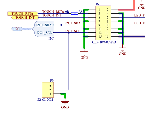
Especially useful for programmable parts, missing debug headers give the software development team a bunch of headaches. Having some simple 2.54mm or 1,27mm pitch headers on serial buses is valuable in helping software teams debug issues with serially connected devices.
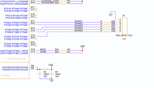
Dedicate some 2-pin headers to GND only, enabling easy use of croc clips for probing. Tying some spare I/Os to a header for an FPGA can allow easy attachment of a logic analyser, giving another useful debug tool, without the need to pick up a soldering iron.

Figure 1. Debug header P3 on serial bus
Keep some I/Os free for test points
Always have some test points to allow easy measurement of all supply voltages and references. It’s helpful to have something you can clip a probe onto, in order for dynamic measurements to be taken. This will leave your hands free for scope controls or working a program.
Have some test points on spare I/Os of micros or FPGAs. If there is something missing and you just need another output or input, those extra I/Os will be a bonus. For instance, a mistake caused a critical interrupt line to be missed off the board – having some I/Os free especially with BGAs can help cure the issue with a simple mod wire.
Always consider the size of the test points and their position. If it’s a high-speed track or critical clock you want to probe, minimise stub tracks to the test point so as not to affect the signal integrity of the signal you are trying to measure.

Figure 2. Connector J2 connected to spare FPGA I/O pins
If it’s an assembly of several boards then having TPs/headers for buses that are accessible on different stages of the assembly aid debug and development later. Reduce the time chasing issues through several boards.
Removing the solder resist from VIAs will help you probe the board – especially useful under BGA device where it has been fanned out to through-hole VIAs.
Use ground connections for probing
Without close GND probing points to complement the test points, you witness an increase in ground impedance and ground loop size as you have to connect the ground of the probe to somewhere far away relative to the test point. Large GND loops act as antennas – picking up a lot of noise from the environment and harming sensitive small signal measurements. Be sure to place convenient clip test points for GND – particularly near areas where you need to carefully measure overshoot and undershoot, such as power supplies and high-speed circuitry.
Make more use of LEDs
Having a few debug LEDs on spare I/O pins can certainly help debug issues – for example, boot loaders sticking before you have managed to bring up a serial port. They can give you quick checks of internal FPGA signals and registers. LEDs attached to power rails provide a quick indication that all the power supply circuitry is operational and save you time hunting for a problem if a rail has been damaged during the course of development.
Add low resistance shunt resistors to power supplies
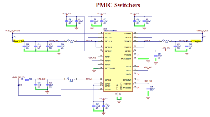
Most designs have some form of power supply and after careful design, there is a need to verify it on the board. Adding a low resistance shunt resistor to the output of the power supply can help with current measurement and check everything meets the design requirements. Load testing with test equipment can be used easily.

Figure 3. Shut resistors added to supply rails. Notice the feedback is after the shunt to correct for voltage drop
Quick fixes for circuit errors
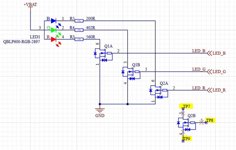
Add resistors or test points to the unused parts of a component. Sometimes, having access to a spare piece of logic, transistor or op-amp can provide a quick fix for circuit errors. Easy access to these components reduces the need to stick components on the board with glue or tape – leading to messy connections.

Figure 4. Spare transistor with test points added
Enable signals
Connect output enable pins using resistors. Don’t tie directly to power in order to disable outputs as required. Tying inputs to power then finding you need to cut a track under a chip is annoying.

Figure 5. Resistor on the enable pin allowing isolation of this bus
Handle interface unknowns
If you are not 100% certain about an interface, then add series 0 ohm resistors and try to route the traces on the PCB surface in case of a mistake. Some of technical reference manuals and datasheets can sometimes be ambiguous about the direction of signals – for example, UARTs with configurable CTS, RTS, TX, RX.
Summary
As well as being, typically, the priciest board on a project, the first prototype of a PCB is also one of the most challenging to develop. Much effort is spent on schematics, simulating, reviewing and calculating. At this point, it’s incredibly important to avoid expensive PCB coasters and losing time to re-spins; these could cost you a launch window or vital first-time customers. Hopefully, these tips will help you avoid some prototyping pains.


