


To combat climate change, vehicle CO2 emissions and fuel consumption must be cut. In many countries, automakers are now legally mandated to make these changes. One way of achieving this is through hybridisation; adding an electric motor to the drive chain in petrol or diesel cars, powered by a second battery.
Traditional electrification has used a high-voltage battery, typically in the 300V to 400V range, coupled to a high-performance electric motor. These ‘full hybrid’ vehicles can deliver significant fuel efficiency but can also add a lot of cost and weight. So-called ‘plug-in’ hybrids, where the battery is charged from an AC outlet, can have similar drawbacks.
An alternative is ‘mild hybrid electric vehicles’ (MHEVs), which use a compact 48V battery to drive an electric motor, which can provide faster acceleration and more low-end torque, while still improving fuel economy and adding only modest increases in cost and complexity. The benefits of a mild hybrid system is popular with consumers, with analyst IHS forecasting that about 50% of hybrid car sales will be 48V mild hybrids by 2025. The lower cost of 48V systems is also attractive to automakers.
.jpg)
Above: Figure 1. A 48V Mild Hybrid Electrical System
Adding a 48V Lithium Ion (Li-Ion) battery means a MHEV is a dual-voltage vehicle, which presents its own design challenges centred on managing the charge and discharge cycles of batteries while maintaining system efficiency. In this article, we’ll discuss these challenges, and explore how power converters can benefit from using automotive power modules, as well as new wide bandgap transistors based on GaN technology.
The 48V architecture
The most basic hybrid system (Figure 1) includes a battery, an integrated starter-generator (ISG), a 48V to 12V converter, and one or more 48V loads, such as a stabilisation system. Since 48V mild hybrids retain the 12V battery and multiple 12V loads, these systems will remain dual voltage architectures for the foreseeable future.
The ISG is responsible for generating the vehicle’s electrical power and for vehicle starting, as well as for regenerative energy recovery during braking.
The 12V battery side of the system remains as is, minus the 12V alternator. Since there is no generator for sourcing 12V power from the ICE, a bidirectional converter is required to transfer the 48V power to the 12V system, and vice-versa.
MHEV bidirectional converter operation
The bidirectional converter has multiple modes of operation. During vehicle start, the current for the ISG is drawn from the 48V Li-Ion battery. If the 48V battery has insufficient charge or is unable to supply enough power (due to cold temperatures, for example), the converter will operate in boost mode, drawing from the 12V battery to provide additional starting current. Typically, the engine start/stop functionality will be inhibited until all systems have reached normal operating temperature, at which point normal vehicle re-starts will commence.
.jpg)
Above: Figure 2. Bidirectional converter – single phase
When the vehicle is warm and driving, but doesn’t require additional acceleration, the converter will operate in buck mode, to deliver current from the 48V battery to charge the 12V battery and supply the 12V loads. When the additional electric is requested, the converter will once again switch into boost mode, to deliver supplement to the ICE, reduce fuel consumption and lower overall emissions.
Converter topologies
The 48V to 12V converter typically has a large power range of 1kW to 3kW. To maintain high efficiency over this range, a multi-stage interleaved buck-boost converter is the most popular choice.
A buck topology provides voltage reduction, in this case 48V to 12V, while a boost topology provides power conversion in the opposite direction. A synchronous topology improves the overall efficiency of a converter by keeping the power switches full-on for the majority of time in both modes.
A multi-phase interleaved design connects several identical converter phases (see Figure 2 for an example of a single phase) in parallel, to function as a single high-power converter. Under heavy load all phases will be operational, but during periods of lighter load some can be switched off using battery-disconnect switches, resulting in lower losses and better efficiency. Each phase produces its output current with a slightly different phase angle, which reduces the ripple at the output capacitors. Using interleaving, rather than a single larger converter, also means that the current in each phase is lower, reducing the stress on the power switches, conductors, and inductor (Figure 3).
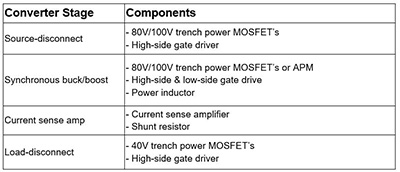
Above: Table 1
The main blocks in such a converter are the source-disconnect switch, buck-boost half-bridge, the current sensing stage, main inductor and the load-disconnect switch.
The synchronous buck-boost converter is actually two switching circuits combined into a single stage. The power switches control current flow in the main energy-converting component; the inductor. The inductor current is the primary variable to be controlled, as it is of paramount importance for maintaining good system accuracy.
The direction of the inductor current determines the direction of the power flow, and thus which battery receives current. The system controller determines the direction of current, by generating the appropriate switch pattern.
Converter design
The main circuit components required are outlined in Table 1. The source-disconnect and load-disconnect stages can both use discrete MOSFETs or an integrated MOSFET power module. The main purpose of these stages is to isolate the input and output, respectively, of each interleaved stage from the other stages and the 48V (source) and 12V (load) battery, using a back-to-back switch configuration. Each device is controlled by a gate driver with high-side drive capability, since these MOSFETs operate at floating voltage potentials. The MOSFETs may need to remain in conduction for extended periods of time, so must be capable of 100% on-time conduction.
The buck-boost stage is the heart of the converter and consists of two MOSFET devices in a half-bridge configuration, connected to the power inductor. These MOSFETs must be controlled by high-side and low-side gate drivers which may be independently packaged or co-packed into a dual driver IC. Alternatively, this stage can be realised using a compact Automotive Power Module (APM).
This ON Semiconductor integrated power module features low thermal resistance, low internal electrical resistance and improved EMI performance, in a compact AEC-qualified package. In this implementation, the source-disconnect circuits are not used. For individual phase isolation the load-disconnect circuitry can be used.
.jpg)
Above: Figure 3. A multi-phase buck-boost converter in an interleaved configuration
The main power inductors store the energy of each converter phase and deliver it to either battery. The converter controller controls the two main switches, which determine the direction of power flow. For this stage to operate correctly the current must be accurately measured, to properly adjust the main inductor current. The use of a current sense amplifier based on a shunt resistor is ideal, as it has extremely low error.
By using a precision shunt resistor, we can measure a very small differential voltage, typically tens or hundreds of millivolts, while the shunt voltage itself can vary from zero to 48V with respect to ground. This large difference means that the amplifier must amplify small differential signals and provide high common mode voltage rejection, while withstanding transient voltages up to 80V. Three amplifier specifications must therefore be carefully selected:
- Common mode voltage range (the wider the better).
- Input offset voltage (the smaller the better).
- Common mode rejection ratio (the higher the better).
In conventional operational amplifiers, the input terminal voltages are limited to the supply rails ±0.6V, thus dramatically limiting the common mode voltage range. In recent years, dedicated current sense amplifiers provide a much larger common mode voltage range, up to 80V. They also provide high precision, as low as 10µV offset, enabling highly accurate and fast current monitoring systems.
Converter design using GaN
With automotive applications demanding improvements in size and efficiency, wide bandgap (WBG) devices, such as those from ON Semiconductor, offer an alternative to standard silicon devices. Gallium nitride (GaN) devices can increase efficiency and reduce size, while decreasing total system cost.
Since GaN devices significantly reduce switching losses, buck converters using GaN can be switched many times faster than typical silicon power transistors, thus minimising EMI interference in frequency ranges that can affect AM radio reception. GaN transistors also do not suffer from reverse recovery loss, thus eliminating the generation of large current spikes and power losses during hard-switching transitions.
.jpg)
Above: Figure 4. Basic buck-boost conversion
Conclusion
With the widespread introduction of many new mild hybrid electric vehicles (MHEVs), more cars now have 48V battery sub-systems, thus requiring a 48V to 12V converter. While many different possible converter topologies are possible, the bidirectional interleaved synchronous buck-boost converter has become the most widespread, due to its simplicity and high efficiency.
This topology can also be designed in multiple interleaved phases, enabling it to achieve high efficiency over a wide operating range. This is important because the 12V vehicle loads vary greatly over time, and even though the converter needs to function at the maximum load point, it seldom stays there for long. When the loading is light, the converter will shed unnecessary interleaved phases, to reduce losses and maintain high efficiency.