


The best technology choice for fully electrical or hybrid powertrains provides optical data networks with their intrinsic electromagnetic compatibility (EMC). Plastic optical fibre (POF) communications is inherently immune to, and robust against, electromagnetic fields. Optical Ethernet provides 100Mb/s and 1Gb/s Ethernet- compatible solutions today, and multi-Gbit in the future, with margin to withstand the harsh automotive environment.
Interference in powertrains
The powertrains of hybrid and electrical vehicles require multiple electronic units placed around the car. These electronic control units (ECUs) regulate and control the electrical flow of the energy between the batteries, converters, and motors/generators. The energy flow and conversion generates electrical noise which will affect other areas of the car, such as the infotainment or navigation systems today and the autonomous control systems tomorrow.
The primary source of electrical noise generation is the continual switching of the IGBTs and MOSFETs embedded within the power electronic subsystems. The DC/AC inverter produces an AC waveform from the battery current that drives the electric motor or, alternatively, rectifies the current from the motor to store it in the battery. On the DC/AC inverter board, AC waveforms on the order of eight to 10kHz are typically generated. The DC/DC bidirectional converter steps up the voltage of the battery pack to that employed on the high voltage bus and generates harmonics in the 50kHz band. Another source of high frequency AC ripple on the DC link comes from the electrical motor itself (Figure 1). The electrical machine produces odd harmonics arising from the non-sinusoidal back-EMF waveform.
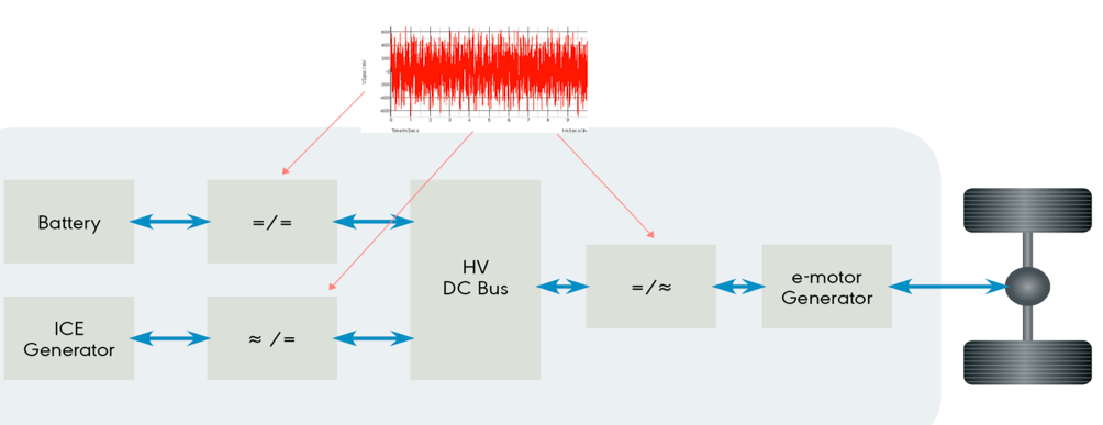 Figure 1: The electrical motor’s effect on high frequency AC ripple on the DC link
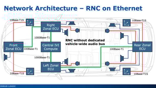
The control of all the subsystems involved in the electrical powertrain requires a communication bus that transports the control, actuation and sensor signals among the different components. The communication bus has to be immune to electromagnetic noise and, at the same time, comply with the mechanical, temperature and weight constraints of the vehicle. An optical-based communication technology like 1000BASE-RH complies with these requirements. Moreover, the bus can be operated at 100Mb/s for most current needs while also supporting future needs at 1Gb/s. By optically connecting the ECUs, it is possible to isolate each noise within the ECU that originates it, avoiding its propagation to all the other ECUs dispersed around the car. Trying to achieve a similar isolation with a copper-based network is difficult and expensive, which translates into a longer engineering development cycle and a more expensive and complex ECU, which may result in lower reliability.
Isolation risks
The batteries used in electrical powertrains consist of physical clusters of cells, assembled in enclosures called packs. Packs typically contain between six and 24 cells in series. Altogether, a commercial battery involves 100 or more cells providing hundreds of volts. A typical lithium-ion (Li-Ion) battery consists of approximately 96 stacks of cells, developing a total voltage in excess of 400V. Above 60V may be lethal to human beings, so safety is a key concern. Although inherently dangerous, stacks need to be monitored and managed. For this purpose, a safe and reliable communication system between the cell monitoring devices in the packs and the central battery management system (BMS) is needed. For Li-Ion chemistry, for example, it is necessary to monitor the voltage of each cell. Although individual cell temperature monitoring is not mandatory, the facility to do so should be available. These measurements are taken by specific standard product ICs (ASSPs), which typically handle six to 12 cells.
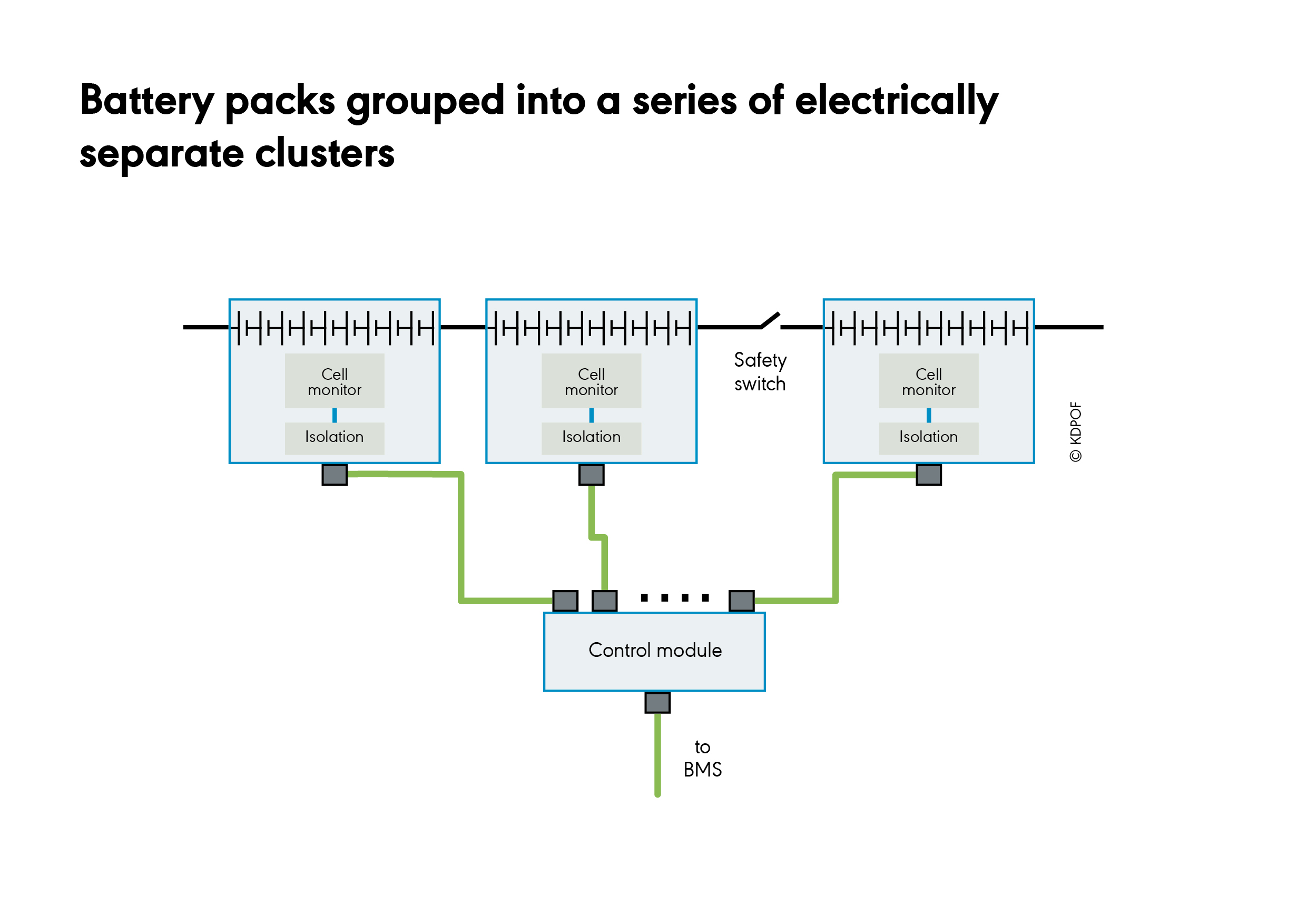
A common approach to organising cells in a battery stack is to group the battery packs into a series of electrically separate clusters, as shown in Figure 2. Each cell pack communicates with a control module that in turn sends and receives control information from the BMS. The chain of cells is connected in series with a switch that is normally closed when the vehicle is in operation. In emergencies, the switch is opened so the stack voltage disappears at the terminals. To avoid compromising the isolation provided by the open switch, it is necessary to ensure that there is no alternative electronic path bridging the switch terminals. The top half of the stack should be electrically isolated from the bottom when the switch is open. The need for a communication bus between each pack of cells and the control module may create an undesired parallel path to the switch, however. Each pack has to communicate with the control module across an isolation barrier. In other words, the communication bus should provide galvanic isolation, yet the cabling required for the communication bus degrades the EMC performance of the system. A communication system not based on copper wires ensures a safe, robust and long-term galvanic isolation between the cell monitoring structures and the BMS.
Fault protection
Mixed 48-/12V systems will be the mainstream in next generation hybrid electric vehicles (HEV) and plug-in HEVs (PHEVs). 48V volts are reserved for “hungry” electrical modules like starters, alternators or battery modules, while 12V modules are dedicated to the more delicate electronic modules like infotainment or advanced driving assistance systems (ADAS) processing units. Both domains share the same ground return path, the car chassis (Figure 3).
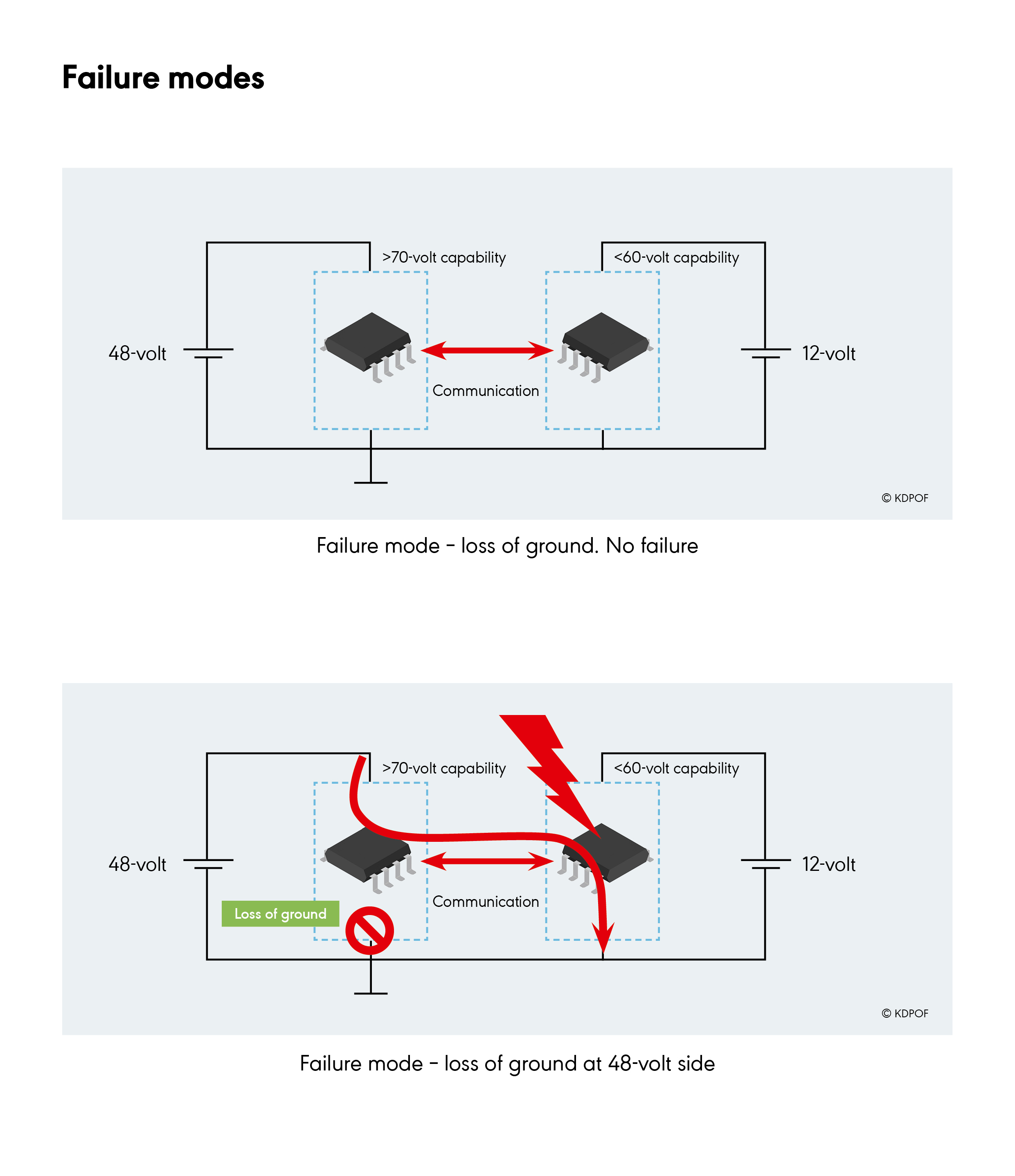
Figure 3: Battery management system failure modes
The ECU in the 48V domain is designed with electronic components sized for such voltages. These components are typically rated to withstand more than 70V. The 12V ECUs are designed with electronic components that typically support up to 60V. In case of an event like a loss of ground in a 48V ECU, and if there are non-galvanic isolated links between the 48V and the 12V domains, there will be an electrical path between the two domains. This will expose the 12V ECUs and their components to voltages higher than the ones they were rated to support, causing failures or a reduction of service life. Galvanic isolation is native in optical networks, so there is no need to include protections to prevent such events or design the 12V ECU to withstand potential events at 48V or higher.
Optical connectivity
POF cables can withstand harsh environments, vibrations, misalignments, dirtiness, humidity and wide temperature range. POF also allows fast dynamic bending, tight static bending and immersion in liquid. Additionally, optical Ethernet generates no noise and can operate in noisy environments, such as in RF electronic boards. As a plastic fibre with a large diameter, POF is more cost-effective to manufacture and install with winding and clamping similar to that for copper cables. Moreover, during car assembly, an optical harness can be installed in the same process as a copper harness. POF has been used in vehicles for more than 10 years and is installed in millions of cars without issues.
Devices such as the fully integrated automotive transceiver, KD1053 implement the physical layer of Gigabit Ethernet over POF (GEPOF). Data transmission of this device is 1,000/100Mb/s on standard step index plastic optical fibre (SI-POF), multi-core plastic optical fibre (MC-POF) or plastic clad silica (PCS), according to 1000BASE-RH (IEEE Std 802.3bvTM-2017). Its flexible connectivity supports multiple digital media access control (MAC) interfaces (media independent interface (MII), reduced MMI (RMII), reduced Gbit MMI (RGMII), serial Gbit MMI (SGMII), 100/1000BASE-X), serial management interface (SMI), e.g management data input/output (MDIO) or management data clock (MDC) interface for management supporting Clauses 22 and 45, which can also be configured as an I2C bus, and SPI/I2C master interface for reading external boot and configuration EEPROM. The transceiver also supports operations, administrations and management (OAM), wake up and sleep, interruption generation, as well as jumbo packets up to 10kB, precision time protocol (PTP), and SyncE clock generation. It offers different loopback modes, polarisation mode dispersal (PMD) test modes for diagnostics, link/activity monitoring and speed LED outputs. Digital adaptive non-linear equalisers are fully integrated. Bit error rate (BER) is less than 10 to 12 for 1Gb/s and 100Mb/s operation modes. Latency is 6.2ms for 1Gb/s operation and 1.4ms for 100Mb/s (local RGMII to remote RGMII); and 5ns root mean square (RMS) jitter for 1Gb/s operation and 9ns for 100Mb/s. Link time for 1 Gb/s operation totals 55ms. Internal dependability functions include power supply voltages, temperature sensors, local and remote link margin, and frequency of optimum transmittion (FOT) input power monitoring. There is also power management with integrated linear voltage regulators and low power consumption of 460mW at 1Gb/s with serial interface.
The IC complies with stringent EMC specs, providing Automotive AEC-Q100 grade 2, -40 to +105°C ambient temperature range and is supplied in a 56-pin QFN (7.0 x 7.0mm) RoHS package.
Author: Carlos Pardo is CEO and co-founder of KDPOF
