


This article investigates what options exist when the engineering team needs to include an antenna as part of the design brief. To aid the reader, we include a section on antenna design basics to help explain some of the terminology involved when selecting an antenna. The article highlights antennas for mounting external to the vehicle, such as for ADAS, GPS, V2X, and those fitted inside an ECU or infotainment system for in-vehicle WiFi and Bluetooth connectivity.
Connectivity and the car
Automotive antennas have come a long way from the simple telescopic aerials used in the 1970s. Back then, in the era before infotainment systems, the only reason we needed an antenna was for the car radio. Today, antennas are required for significantly more functions. The infotainment system alone hosts the radio, the navigation system, and wireless connectivity to smartphones.
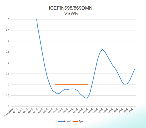
Above: Figure 1 – A VSWR chart of a PulseLarsen Low profile antenna ICEFIN series (source PulseLarsen)
Some aspects of advanced driver assistance systems (ADAS) also require wireless connectivity to other cloud-based services for traffic routing and, shortly, more sophisticated vehicle-to-vehicle (V2V/C2C) and vehicle-to-infrastructure (V2X/C2X) functions. Within the vehicle, wireless communication is used to provide WiFi for passengers’ convenience and communication between different functions – for example, blind-spot detection indicators in door mirrors.
The era of the connected car is now, and the humble antenna plays a critical role in providing reliable and resilient wireless communication both within the vehicle and to external services.
Selecting a suitable antenna requires a good understanding of the application needs, of which the operating frequency is the initial parameter. Today’s vehicle radio tuner rarely have medium wave (530kHz to 1,700kHz) or longwave (150kHz – 250kHz) band options, with very high frequency (VHF) frequency modulated (FM) broadcast radio (80MHz – 108MHz) the most popular. However, the advent of higher-quality digital radio, such as the UK’s digital audio broadcasting (DAB), uses the 175 to 240MHz spectrum.
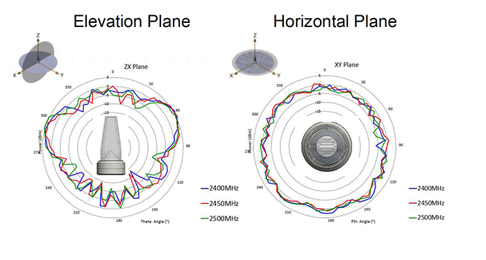
Above: Figure 2 – Radiation characteristics of a PulseLarsen ICEFIN antenna (source PulseLarsen)
Aside from broadcast radio, the primary frequency ranges include WiFi and Bluetooth – 2.4GHz, GNSS – 1.1GHz to 1.6GHz, and cellular phones – 700MHz, 850MHz, and 1,700MHz to 2,100MHz. In addition, 5G cellular communication adds 6GHz to the previous list. Most V2X/V2V applications use cellular communication methods centred around 5.9GHz.
Antenna types
Antennas broadly fall into external and internal categories.
External antennas are typically mounted on the vehicle’s roof towards the rear to minimise any electrical interference from the engine. In addition to the antenna’s electrical characteristics, which are covered in the next section, the need to protect the antenna from the ingress of moisture, dust, and other contaminants is vital. The international IP standards define ingress protection.
Above: Figure 2 – Radiation characteristics of a PulseLarsen ICEFIN antenna (source PulseLarsen)
Exposed to weather excesses, the antenna needs to function reliably when wet, frozen, or subjected to high winds. Many external antennas are packaged inside a ‘sharks fin’ style of plastic casing to satisfy vehicle aesthetics and environmental factors. The casing is streamlined, and the material can be overpainted with the colour of the vehicle. Other external antennas include a ‘puck’ style device that is often magnetically attached to the vehicle’s body. Many external antennas combine several antennas within a single enclosure but all separately wired – GNSS, cellular/5G, and V2X/V2C.
Internal antennas are slightly more diverse and are typically either PCB mounted or etched as a PCB track. Some internal antennas are intended to be mounted externally to the attached system and are usually supplied with a self-adhesive mounting pad and a coaxial cable to the embedded system.
Antenna basics
When selecting an antenna for your application, there are several key parameters you need to consider. An antenna’s performance has several distinct attributes that ensure the most efficient transfer of radio frequency energy from the transmitter to the antenna to be radiated into free space.
The transmitter’s output is sent along a transmission line, such as a coaxial cable, to the antenna. Likewise, received signals also need to be efficiently picked up by the antenna and transferred to the receiver. An antenna is a length of wire in its simplest form, the length of which is determined by the frequency at which it needs to operate. An antenna is resonant when its length is equal to the wavelength, measured in metres, of the transmitted or received signal. For example, a frequency of 2.4GHz has a wavelength of 12.5cm.

Above: Figure 4 Taoglas Raptor 3 shark fin externally mounted antenna (source Taoglas)
In most cases, the efficiency of an antenna is limited to a narrow frequency range. Antennas are constructed in many different ways, the simplest of which is a dipole. Dipoles are typically described relative to their operating wavelength, i.e., a full-wave or a half-wave dipole.
To aid selection and reading antenna sheets, here are some short explanations of the key parameters you might encounter:
Return loss: This term indicates how well the antenna is matched to the transmitter’s output section and the transmission line. Return loss is expressed in dB and indicates how much of the transmitter’s output is reflected from the antenna and transmission line due to mismatching. Most antennas exhibit a 50-ohm impedance, so they will need to be matched to the transmission line and transmitter final stage.
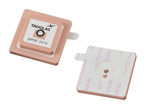
Above: Figure 5 – The Taoglas GPDF357 GNSS antenna (source Taoglas)
The higher the return loss in dB, the less the reflected power. A perfect match results in an almost infinite return loss. Another way of measuring return loss is with the voltage standing wave ratio (VSWR). VSWR indicates the ratio between the power at the transmitter output and the amount of power reflected. A perfect match is expressed as a VSWR 1 (also 1:1). The VSWR or return loss parameter is indicated on an antenna datasheet at a specific frequency or across a narrow band of operating frequencies.
A VSWR of 2 indicates a return loss of 10dB, and these metrics are used as a best practice benchmark a design should target.
Datasheets usually include graphs of antenna VSWR and return loss performance against frequency. Figure 1 illustrates the VSWR chart of a PulseLarsen antenna, with the optimum operating frequency range of 650MHz to 880MHz for cellular or ISM communications.
Radiation Pattern and Antenna Gain: Figure 2 highlights the radiation pattern characteristics of a PulseLarsen ICEFIN antenna. The construction of some antennas makes them more effective at radiating RF energy in some directions than others. An antenna is said to exhibit a gain where the amount of radiated power in a given direction is greater than the input power to the antenna. An omnidirectional radiation pattern is considered ideal for most practical purposes, and the plane characteristics (vertical/elevation or horizontal) is essential for some applications. Note that the antenna characteristics are equally important for the receiver performance as well as for transmitting.

Above: Figure 6 – Taoglas MA354 compact external magnetically mounted antenna (source Taogla)
Impedance matching: As mentioned earlier, most antennas offer a 50ohm impedance. The antenna needs to be matched to the output impedance of the transmitter as well as the transmission line. This will probably be a coaxial cable with the correct impedance for external antennas, but it must match that of the antenna if you have to add the cable. For PCB antennas, it may be necessary to create a matching network, typically of inductors and capacitors, between the transceiver IC and the printed or surface mounted antenna. The impedance changes with frequency.
Impedance and return loss/VSWR characteristics of an antenna are measured with a specialist item of test equipment termed a vector network analyser (VNA). VNAs are available as standalone instruments or incorporated into high-end RF spectrum analysers.
Above: Figure 7 PulseLarsen IceFin multi-band antenna (source PulseLarsen)
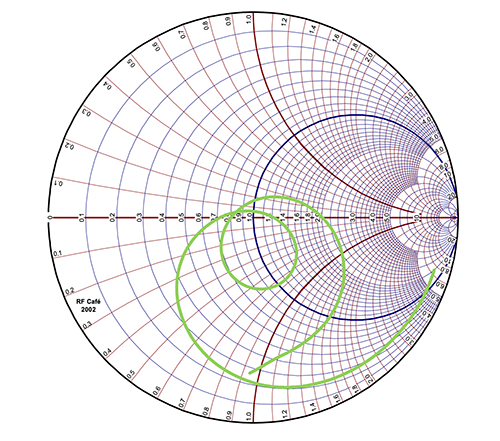
A VNA typically incorporates many test functions with graphical displays such as VSWR and return loss and impedance. Antenna impedance is typically displayed as a Smith chart – see Figure 3.
In brief, the centre line (red) of the chart is a resistive impedance; above, it becomes inductive, below capacitive. The right-hand side is an open circuit, and the left-hand side a short circuit. The green curve highlights how the antenna’s impedance changes with frequency. The 1.0 position on the red line indicates a perfect match of the antenna impedance.
Example antennas
The Taoglas Raptor 3 – see Figure 4 – is an example of an externally mounted sharks-fin IP67 rated style antenna. Suiting automotive and commercial vehicle applications, the antenna combines multiple antennas in one package, offering GNSS, 4G/5G cellular MIMO, dual-band WiFi, an active AM/FM antenna, and TETRA(trunked radio).
For GNSS applications, the internally mounted embedded patch-style Taoglas GPDF357 supports all the GPS and Galileo bands and offers good gain and omnidirectional capabilities. In addition, the compact antenna – see Figure 5 – is suitable for a range of high-precision positioning applications for smart agriculture and public safety.
Another multi-band antenna is the externally mounted 4-in-1 Taoglas MA354. This low-profile compact IP65 rated antenna features an integrated magnetic mount for a quick no-drill installation on a vehicle. Five internal antennas support dual-band WiFi, 4G/5G with 3G/2G compatibility, and GNSS.
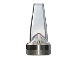
Another externally mounted IP67-rated multi-band antenna is the PulseLarsen IceFin series – see Figure 7. The series offers antennas across a range of frequencies from 698MHz to 6,000MHz.
PulseLarsen also provides a series of antenna kits incorporating various embedded, internal, and external antennas for prototyping and development purposes. The kits are available in three versions: Instrumentation, Scientific, and Medical (ISM) antenna kit, LoRa antenna kit and Internet of Things (IoT). An example is the IoT Antenna Kit, which comprises 26 different antennas suitable for IoT applications using dual-band WiFi, cellular, and GNSS connectivity. The antenna types include ceramic, helical, PCB, stick, and blade variants.
Reliability requires the right antenna
In this article, we’ve covered the essential information to help guide your antenna selection process. We’ve covered some of the popular antenna types and illustrated some examples. To help understand datasheet information, we’ve briefly introduced some of the key antenna parameters you need to be aware of to select an antenna fit for your application.