


This article originally appeared in the Feb’23 magazine issue of Electronic Specifier Design – see ES’s Magazine Archives for more featured publications.
More efficiency for controlled drives and power converters
The remarkable performance of today’s EVs and HEVs results in a large part from the electronic control in drives and power converters. Real-time microcontrollers (MCUs) used in these subsystems employ complex control algorithms and accurate motor models to respond extremely quickly, with a control delay of only a few microseconds (µs).
To enable the use of proportional-integral-derivative (PID) controllers from standard libraries, vector controllers transform the three-phase stator current system into a two-dimensional current space vector to control magnetic flux density and rotor torque. A fast current loop (blue arrow in Figure 1) should achieve a control delay of less than 1µs.
Combining fast vector control such as field-oriented control (FOC) and a highly efficient internal permanent magnet synchronous reluctance motor (IPM-SynRM), motor drives achieve large torques and up to 96% efficiency. Designers can implement variable torque control between the Lorentz force and reluctance force of the IPM-SynRM using a C2000 series real-time MCU and C2000WARE-MOTORCONTROL-SDK software in a time and cost-efficient manner.
For AC-DC power converters operating as EV on-board chargers (OBCs), or conversely as photovoltaic inverters, it is important to keep the power grid free from harmonic distortion. This unclean zero voltage switching (ZVS) can be counteracted with hybrid hysteretic control (HHC) of current. Here, developers can also rely on C2000 MCUs to accelerate circuit design by applying high-performance control algorithms from the C2000WARE-DIGITALPOW-ER-SDK software repository.
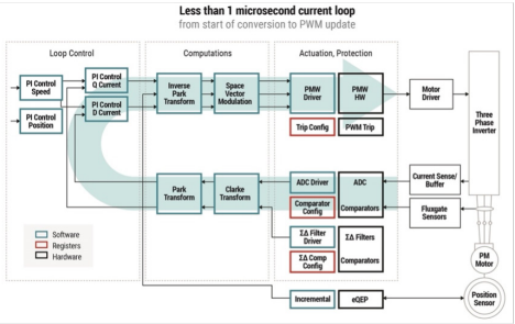 Figure 1. For stable control, a real-time MCU must complete all arithmetic operations per loop pass in less than 1µs (Image source: Texas Instruments)
Simplify EV system design using C2000 MCUs
To simplify power system design, Texas Instruments offers the C2000 series real-time MCUs. System designers can use a single powerful MCU to control multiple power electronics and system components distributed throughout the vehicle. The TI website, particularly the Resource Explorer and C2000 Academy, provides designers with support.
TI has optimised the F28003x family of real-time controllers specifically for use in EVs. Offering 240 MIPS of processing power and integrated real-time control peripherals, circuit designers can improve the precision and energy efficiency of their motor control and power conversion systems based on an F280039CSPZ MCU – without the need for an FPGA. Additionally, easy-to-implement GaN and SiC technology reduces switching losses and increases power density.
The F28003x series supports Controller Area Network Full Duplex (CAN FD) communications as well as several fast serial interfaces. On-chip security features such as Secure Boot, an AES encryption engine, JTAG lock, and hardware built-in self-test (HWBIST) ensure networked system interventions such as live firmware and firmware-over-the-air (FOTA) updates are secure against tampering. Figure 2 provides an overview of essential functions and interfaces.
 Figure 2. Function block diagram of the F280039C MCU showing product highlights (Image source: Texas-instruments)
Ideal for testing and prototyping, the TMDSCNCD280039C is a suitable evaluation board for the F280039C. To operate this controlCARD equipped with an HSEC180 header (180-pin high-speed edge connector), a TMDSHSECDOCK 180-pin docking station is required.
Configurable logic blocks (CLBs) for custom logic
Innovative configurable logic blocks (CLBs) allow programmers to integrate custom logic into the C2000 real-time control system while eliminating external logic, FPGAs, CPLDs or ASICs. By adding a CLB, existing C2000 peripheral modules such as enhanced pulse width modulator (ePWM), enhanced capture (eCAP), or enhanced quadrature encoder pulse (eQEP) can be extended with customer-specific signals and functions.
The logic blocks are configured via C2000 SysConfig, which is available within C2000Ware. It requires the SysConfig tool which is part of TI’s Code Composer Studio (CCS) integrated development environment (IDE), or is available as a standalone tool for use with other IDEs (Figure 3).
The C2000Ware software and documentation package minimises development time by providing extensive device-specific drivers, libraries, and application examples.
Clocking and testing
Instead of intervening in the complex clock periphery using CLBs, programmers can use the Embedded Pattern Generator (EPG) for simple test scenarios during programming or validation. The standalone EPG module facilitates the generation of custom pulse patterns (SIGGEN) and clock signals (CLOCKGEN), but it can also capture and reshape an incoming serial data stream or synchronise with generated clock signals.
For debug and the monitoring and profiling of critical CPU buses and device events in a non-intrusive way in a C2000 real-time system, Embedded Real-Time Analysis & Diagnostics (ERAD) is used. The hardware module offers extended bus comparators and system event counters located within the MCU bus architecture (Figure 4).
ERAD can independently generate system-level interrupts and flags and also feed them into other peripherals such as the CLB.
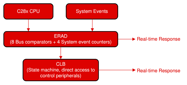
Figure 4. ERAD provides advanced bus comparators and system event counters (Image source: Texas Instruments)
Implement FOC engine controls faster using C2000 MCUs
The implementation of the variable torque control of an IPM-SynRM using a vector control is complex. The complex control of magnetic flux density and rotor torque can be implemented quickly using TI’s Motor Control Software Development Kit.
The software includes firmware that runs on C2000 motor control evaluation modules (EVMs) and TI designs (TIDs). Two key function libraries for vector control are InstaSPIN-FOC (FOC motor controls without encoders) and DesignDRIVE (FOC motor controls requiring encoders).
Key features of InstaSPIN-FOC:
• Sensorless torque or velocity FOC
• Flux, angle, speed, and torque (FAST) software observer for rotor estimations
• Motor parameter identification
• Observer and torque control loop automatic tuning
• Premium performance for low speed and highly dynamic applications
A special feature of the FOC control loop is the adaptive FAST algorithm. This automatically determines flux density, current angle, speed, and torque from the phase voltages and currents (Figure 5).
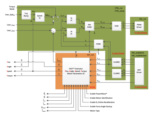
Figure 5. A special feature of the FOC control loop, the adaptive FAST algorithm, automatically detects flux density, current angle, speed, and torque (Image source: Texas Instruments)
Key features of DesignDRIVE:
• Sensored velocity or position FOC
• Position feedback: Resolver, incremental and absolute encoders
• Current sense techniques: Low-side shunt, in-line current sampling, and sigma-delta filter demodulation
• Fast current loop (FCL): Optimised software library that takes full advantage of hardware resources to accelerate the sampling, processing, and actuation of the system
• Real-time connectivity examples
Application example 1: One MCU controls traction inverter and DC-DC converter
Automotive manufacturers tend to merge the three distributed system components into one chassis and minimise the number of MCUs, reducing system cost and complexity. However, this requires an MCU with high real-time control performance.
To address this, TI’s TIDM-02009 reference design demonstrates the combination design of an EV/HEV traction inverter and a bidirectional DC-DC converter controlled by one single F28388DPTPS real-time MCU (Figure 6).
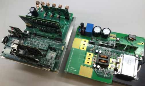
Figure 6: Only one C2000 MCU card of the control board (bottom left) controls the traction inverter (top left) and DC-DC converter (right) (Image source: Texas Instruments)
The traction inverter uses a software-based resolver-to-digital converter (RDC) to drive the motor to a high speed of up to 20,000 revolutions per minute (rpm). Its power stage consists of Wolfspeed’s CCS050M12CM2 six-way power module based on SiC FETs, driven by a TI UCC5870QDWJRQ1 intelligent gate driver. A PWM module with integrated slope compensation in the comparator subsystem (CMPSS) generates the PCMC waveform. The voltage sensing path uses TI’s AMC1311QDWVRQ1 extra-high-isolation amplifiers with 2-volt inputs, and the current sensing path uses TI’s AMC1302QDWVRQ1 extra-high-isolation precision amplifiers with ±50 millivolt (mV) inputs.
The DC-DC converter uses peak current mode control (PCMC) technology with phase-shifted full-bridge topology (PSFB) and synchronous rectification (SR). The CAN FD-based interference-resistant communication is provided by the integrated TCAN4550RGYTQ1 controller transceiver module.
Application example 2: Efficient bidirectional 6.6kW AC-DC converter
For relatively high power outputs, the PMP22650 represents a GaN FET-based reference design for a bidirectional single-phase AC-DC converter handling 6.6 kilowatts (kW) of power. The charger OBC can charge the traction battery with power from the grid and, conversely, pre-charge the DC link capacitors. The device converts 240 volts AC at 28 amperes (A) on the primary side to 350 volts DC at 19 A on the secondary side.
A single F28388DPTPS MCU controls the two-phase totem pole power factor corrected (PFC) link operating at a 120 kilohertz (kHz) switching frequency, and a full-bridge CLLLC (C = capacitor, L = inductor) topology followed by synchronous rectification. The CLLLC converter uses both frequency and phase modulation for output regulation and operates at a variable frequency from 200kHz to 800kHz.
In Figure 7, the matching TMDSCNCD28388D controller card (centre) controls the primary-side PFC intermediate circuit (left) and the secondary-side full-bridge CLLLC converter with synchronous rectification (right) (schematic design in Figure 8).
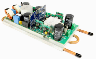
Figure 7: The TMDSCNCD28388D controller card (centre) controls the primary-side PFC link (left) and the secondary-side full-bridge CLLLC converter with synchronous rectification (right) (Image source: Texas Instruments)
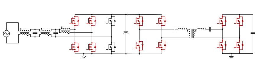
Figure 8: Circuit topology of the OBC consisting of the PFC intermediate circuit (left) and the secondary-side full-bridge CLLLC converters with synchronous rectification (right. (Image source: Texas Instruments)
Efficiency of up to 96% at full power and an open-frame power density of 3.8kW/ liter are made possible by the use of newly developed LMG3522R030-Q1 high-speed GaN FETs. The power factor is 0.999 with less than two percent total harmonic distortion (THD). An alternative to the LMG3522 is the LMG3422R030RQZT GaN FET, also automotive qualified, with a 600 volt switching voltage and an Rds(ON) of 30 milliohms (mΩ).
A special feature of this AC-DC converter is the HHC, which significantly reduces zero-crossing distortion by emulating the voltage across the resonant capacitor. The example of a photovoltaic inverter shows how effectively HHC reduces distortion of the bridge switching transistors at zero crossing (Figure 9, left), thus eliminating emission as well as distortions on the Figure 9: HHC can significantly reduce the distortion of the bridge switching transistors at zero crossing (left) (Image source: ietresearch.onlinelibrary.wiley.com) power grid. The high 7.8% THD of the 3rd harmonic on the sinusoidal grid voltage (Figure 9, top right) is reduced to 0.9% by using HHC (Figure 9).
Incidentally, the circuit design of this 6.6 kW DC-DC converter is based on TI’s TIDA-010062 reference design, while the C2000WARE-DIGITALPOWER-SDK, mentioned earlier, facilitates the design of such power converters.
Conclusion
Texas Instruments’ C2000 series real-time MCUs can tackle almost any control task in automotive power electronics. The application of these MCU ecosystems enables system design in a time and cost-efficient manner by aggregating and jointly controlling what would typically be distributed system electronics using powerful real-time MCUs.
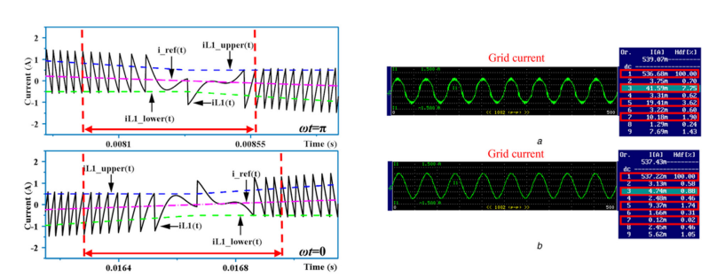
Figure 9: HHC can significantly reduce the distortion of the bridge switching transistors at zero crossing (left) (Image source: ietresearch.onlinelibrary.wiley.com)