


Operating at millimetRE-wave (mmWave) frequencies introduces a set of engineering challenges that extend far beyond traditional radio frequency (RF) testing. Engineers face increasingly severe RF path loss, complex wideband waveforms, stringent link budgets, and the need for coherent multi-channel operation for beamforming and massive MIMO (Multiple-Input Multiple-Output).
These realities demand instrumentation that is not only accurate but also adaptable to evolving standards like 5G New Radio (NR), complex radar algorithms, and beyond. The solution is not a single instrument but a system level approach that minimises loss, preserves phase and amplitude fidelity, and keeps the testbed flexible as standards and architectures evolve. Key elements of that approach are localising frequency conversion near the device under test, reducing long RF runs, designing for wide instantaneous bandwidth, and building modular synchronisation and signal chain access so measurements remain repeatable as test complexity scales.
Frequency coverage
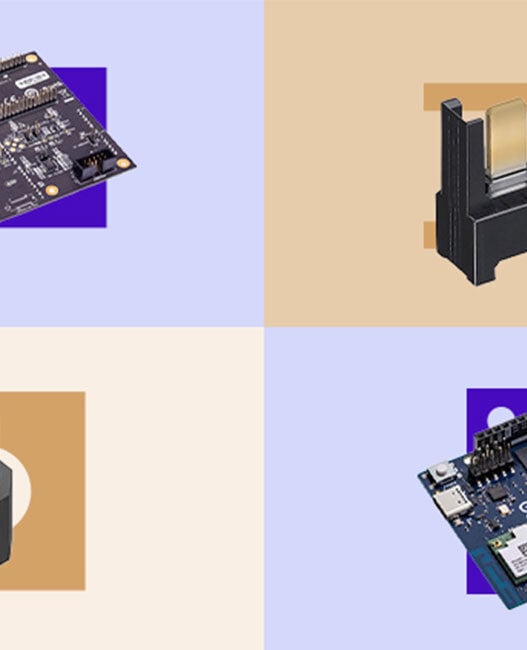
Modern wireless systems span a wide range of spectrum allocations, from sub-6 gigahertz cellular and WLAN bands to mmWave allocations in the 24-52GHz range (5G FR2). Aerospace and defence applications extend this further into K and V bands for radar and satellite communications. A practical test strategy treats frequency coverage as a continuum rather than a set of isolated bands. Consolidating test capability onto a modular platform reduces the number of interconnects and calibration steps, which in turn lowers insertion loss and mismatch risk. Architectures that combine broad IF coverage with optional mmWave front ends let engineers validate everything from baseband conversion stages to over the air performance without constantly reconfiguring hardware. Emerson’s NI PXIe-5842 Vector Signal Transceiver (VST) [Fig. 1], with frequency extension up to 54GHz is one example of this type of test platform, providing continuous coverage from 30 megahertz to 54GHz in a common platform.
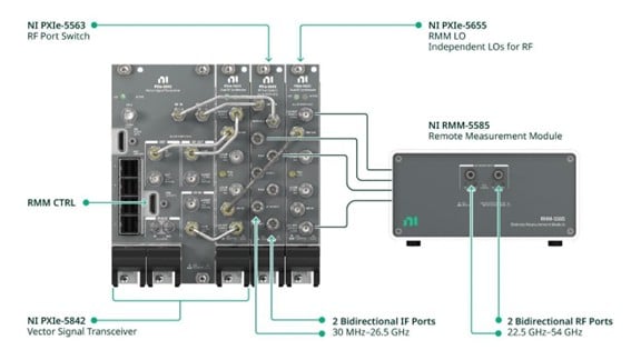
Addressing losses at mmWave
One of the most pressing engineering challenges at mmWave is signal loss. Coaxial cables and connectors exhibit significant attenuation at 28GHz and above, often exceeding several decibels per meter. This loss directly impacts measurement accuracy and power delivery to the device under test (DUT). One effective mitigation tactic is to move the high-frequency conversion as close to the DUT as possible, convert to an intermediate frequency locally, and carry signals back to the main chassis over lower-loss IF paths. That pattern preserves delivered power, improves measurement accuracy, and enables simultaneous transmit and receive paths with independent tuning.
Removable remote modules provide added flexibility for engineers who need to switch between mmWave and sub-6GHz test scenarios without duplicating hardware. This also enables simultaneous transmit and receive operations with independent frequency tuning, supporting diverse test configurations such as loopback validation, beamformer characterisation, and bidirectional link testing.
Bandwidth and modulation fidelity
Next-generation wireless systems demand wider bandwidths and strict linearity to support higher data rates. Standards such as 5G NR and Wi-Fi 7/8 specify channel bandwidths up to 400MHz, with carrier aggregation pushing aggregate bandwidths into the GHz range. Radar systems and electronic warfare applications similarly require wide instantaneous bandwidths for target simulation and spectrum monitoring.
A system-level test solution pairs wideband front ends with internal calibration and amplitude/phase corrections so engineers can capture and reproduce wideband signals without stitching multiple measurements. Maintaining low error vector magnitude across aggregated carriers and wide channels is essential for validating digital predistortion (DPD) algorithms, multi-carrier throughput, and advanced modulation schemes.
Synchronisation and MIMO test
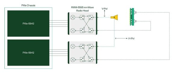
MIMO and beamforming architecture introduce synchronisation challenges. Multiple antennas must operate coherently, requiring sub-nanosecond alignment across channels. Traditional test setups often struggle to maintain phase coherence when scaling to dozens of ports.
Scalable synchronisation is therefore a core system requirement: shared reference distribution, deterministic trigger and timestamping, and modular clocking that scales across instruments. Architectures that provide coherent low oscillator (LO) sharing and tight timing distribution let teams validate phased arrays, multi-emitter scenarios, and multi-port antenna systems without ad hoc external synchronisation hardware.
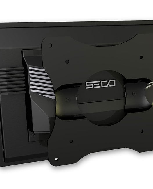
For example, engineers can synchronise two instruments within a single chassis [Fig. 2] or expand across multiple chassis using MXI links. This capability is essential for validating dual-polarisation antennas, multi-emitter threat generation in EW systems, or large-scale MIMO arrays in 5G base stations. By sharing LO signals across modules, the system ensures coherent operation without requiring external synchronisation hardware.
Multiband test ports and signal chain mapping
Modern radio frequency integrated circuits (RFIC) often integrate multiple frequency conversions, beamforming stages, and phased-array outputs. Testing such devices requires access to both IF and RF points in the signal chain. Instruments that provide bidirectional test ports for both IF (30MHz–26.5GHz) and mmWave (22.5–54GHz) frequencies eliminate the need for external switching or conditioning, reducing system complexity and improving repeatability.
For example, when testing a beamformer IC with built-in up-conversion, engineers can connect directly to IF ports to validate conversion stages while simultaneously accessing mmWave ports to measure radiation patterns. This dual-access approach supports comprehensive validation without reconfiguring the test bench.
System-level applications
5G OTA validation – Over-the-air (OTA) chamber measurements for beamforming arrays require minimised path loss and accurate chamber stimulus and capture.
Radar and electronic warfare – wideband record/playback and multi-emitter generation depend on bandwidth and tight synchronisation.
SATCOM and high-frequency links – telemetry and datalink validation benefit from architectures that reach into higher bands while preserving IF-level fidelity.
Prototyping and production test – flexible, reconfigurable testbeds reduce hardware duplication and speed transitions from research and development to manufacturing.
Conclusion
The transition to mmWave frequencies forces engineers to confront challenges in loss management, bandwidth fidelity, synchronisation, and multiband integration. Test instruments and architectures that address these by combining wide frequency coverage, local frequency conversion, high earned value management (EVM) performance, and phase-coherent synchronisation provide a robust ecosystem for these new challenges. For system-level test environments – whether validating 5G base stations, user equipment, qualifying satellite communication (SATCOM) links, or prototyping radar arrays – these solutions provide a technically reasoned approach that reduces complexity while meeting stringent performance requirements.