


Resistance is an electric circuit component, which is characterised by energy losses in a circuit as heat, some mechanical work, or electromagnetic radiation.
No matter how complex electric circuit is, it always can be reduced into series and parallel form.
Two or more circuit elements are in series if identical current flows through each of this elements. Series resistance are connected in chain so the same current is flowing across all resistors.
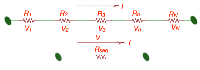
Here . These resistors in series can be replaced with the equivalent resistance , that can replace chain of resistors in a circuit with serious connection. Here .
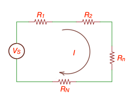
resistors are connected in series one to the other forms voltage divider circuit. We can apply Kirhhoff’s Laws to the circuit , and .
The voltage across every resistor as , here is a source voltage.
This circuit is called voltage divider. Voltage divider is a linear circuit that produces output voltage equal to fraction of the input voltage. If we know all resistances in the circuit and battery voltage (or source voltage), we can find voltage drop of every resistor.
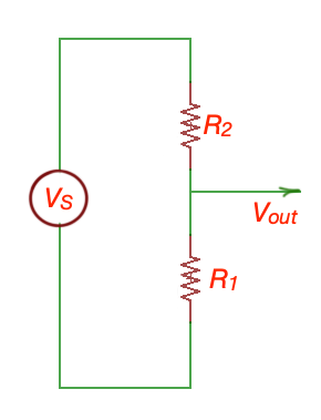
For example, If Ohm, Ohm, and , thenV.