


The number of battery-run electric vehicles (BEVs) on the road is rising rapidly, especially since their retail price is becoming more accessible and their driving range being significantly extended.
BEV makers continue to improve their vehicles, encouraging their further widespread adoption. However, there are still challenges that design engineers continue to address, especially to optimise BEV’s driving range. These include but are not limited to lowering the size, weight, and cost of BEV systems and components whilst increasing their performance and safety. Here, devices like current sensors make a significant difference. They are found in the BEVs’ battery management systems (BMS) and on-board chargers (OBCs), monitoring and measuring currents flowing in or out of these systems, and detecting and measuring leakage currents for safety, preventing risks of electric shock or fire.

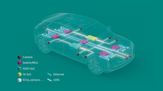
Current sensors in BEV motor control
In motor control (Figure 1), current sensors monitor and measure the current flowing through the motor that propels the vehicle, and enable its proper and safe operation. Here, current sensors are used in three important stages: the DC link, phase measurement, and rotor excitation.
A DC link is, in effect, the ‘connector’ between the rectifier (converting input AC to DC needed by the battery for its operation) and the inverter (which converts DC to AC to drive the motor). The DC link consists of capacitors.
To keep the DC voltage from the battery pack stable at all times, the DC link section monitors and manages the current with current sensors. This is an important stage in motor control, but integration trends have seen it being replaced by either the BMS or the battery disconnect unit (BDU).
In BEVs, power motors can be 50kW or above, and use three phase inverters; in high-performance vehicles this rises to 6-phase inverters. The inverter’s output current drives each phase of the motor, to create a magnetic field that powers the motor’s rotation. Each phase has its own, independent current sensor at the output of the inverter, to monitor the current. Two current sensors can be sufficient for safe operation here, with the current in the third phase being derived from the sum of the other two phases. However, for utmost safety and reliability, designers tend to apply three current sensors at this stage.
The inverter’s current manages the motor’s torque and speed by controlling the frequency and amplitude of the current delivered to each phase, enabled by the current sensors. To ensure that the inverter sends the right amount of current into the motor, the output of the current sensors is fed into a control loop.
Current sensors also play a pivotal role at the rotor excitation stage, and, here, the objective is to measure the direct current for precise control of the wound rotor.
Sensor miniaturisation and integration
For all the stages in BEVs’ motor control, miniaturisation continues to play a key role, and, here, semiconductor innovation introduces better, smarter and cheaper sensors. For minimal footprint and lower costs, mechanical integration has been adopted by many sensor makers, including LEM. Integration can be of the power module or the sensor itself.
Integration adds greater power density in a sensing unit, and provides best lifetime performance due to a combination of end-of-line full calibration that allows plug-and-play implementation, best mechanical and electrical coupling, high accuracy thanks to magnetic concentration, and good crosstalk suppression thanks to the magnetic core.
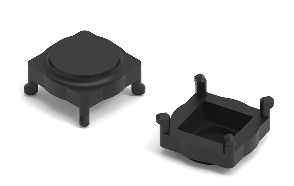
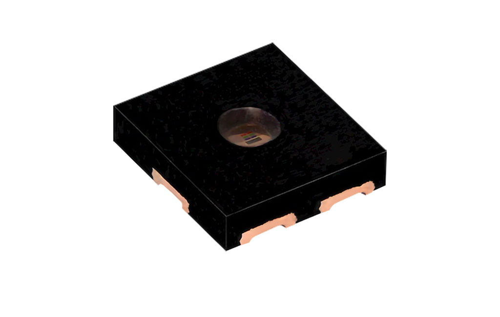
At present, a major innovation in the industry are coreless designs, for reduced footprint and cost and easier design-in; see Figure 2.

A true coreless design removes the magnetic core from the current sensor module, and is the best option to reduce the total package size, but imposes new form factors and requires solving some performance challenges: Better accuracy requires better coupling, less crosstalk, better linearity over a very large current range, which in turn needs better semiconductors, better mechanical concepts, greater collaboration with OEMs, and so on.
Meeting industry challenges
With experience and application knowledge spanning over 50 years, LEM has attained expertise in key domains crucial to current sensor design, including mechanical concepts, sensing technologies and calibration, integration approaches, chip designs and software development, but also meeting various norms and regulations for different regions.
LEM has built its expertise in the motor control area since the 1990s, changing and adapting its portfolio in sync with the market. Its continual market research and close cooperation with its customers has helped it identify market needs well before trends have taken hold. Thus, it continues to anticipate customer needs at each stage of BEV developments, and motor control systems are a big part of it – the DC link, phase control and rotor excitation. LEM offers a comprehensive range of current sensing products to tend to these applications and continues to innovate and reinvent its standard and custom solutions.
For the DC link section, LEM provides various types of current sensors, which can be off-the-shelf (OTS) or custom. These include its single-phase, HSNDR, HSTDR, HAM and HAH1 devices, which come in different mechanical form factors.
For the phase monitoring stage in motor control, LEM offers a wide portfolio of current sensors, including its HAH2 for two-phase, HAH3 for three-phase, but also custom current sensor designs.
As for rotor excitation and the current being monitored here, LEM’s HMSR, GO and advanced ICS (to be introduced this year) are the perfect solution.
LEM works directly with OEMs and Tier 1 suppliers to co-design solutions, too, to address any challenge that may arise in creating the required automotive control system. Through its approach to mechanical integration and with an efficient manufacturing process, it can offer more accurate calibration of the current sensors. Collaborating closely with OEM and Tier-1 companies’ R&D teams from the outset will help achieve the best integration of the current sensing function into the system from the start.
Finding the right partners, those who anticipate customer needs at an early stage and provide thought-through, high-performing solutions, will help companies accelerate their design time and shrink the time-to-market curve.
About the author:
Charles Flatot-Le Bohec, Global Product Manager for Motor Control for Automotive at LEM