
Addressing test amplifier distortion
Following publication of the third addition, test engineers may need to review their choice of amplifier, in order to continue to comply with the new IEC 61000-4-3. By John Dearing, product manager for the Teseq range of RF broadband power amplifiers and Compliance 3 test software.
The third edition of IEC 61000-4-3, published in 2006, has mandated changes in some key areas that may require the replacement of radiated immunity test amplifiers. Along with extending the test frequency range to 6GHz and better defining the calibration of the uniform field, the standard requires verification of the power amplifier linearity and output harmonics. As a result, some existing systems may fail to meet the new requirements because the amplifier in use is being run near saturation and, consequently, the modulated field is distorted.
.png)
Figure 1: The maximum power that can be supplied at a given frequency (saturation)
A linear relationship exists between the input power and output power over most of the operating range of an amplifier. However as the power level rises, limitations in the supply voltage and/or current cause the output power to increase at a slower rate than the input. This is the start of the amplifier going into saturation. The relationship between input power and output power starts to roll off and eventually reaches a point where increases in the input power cause no change in the output power. This is the saturation point and is the maximum power that can be supplied by the amplifier at a given frequency (See Figure 1). Note that this saturated power level will vary with frequency.
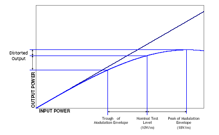
Figure 2: Output distortion caused by operating beyond the amplifier’s linear region
Most amplifier suppliers use this saturated power figure to define the performance of the amplifier, however in the case of IEC61000-4-3 testing this figure is not useful for selecting an amplifier or predicting compliance with the standard. Since the test requires that the RF test field is sine wave amplitude modulated, the input level is effectively increasing and decreasing around the nominal test level. If the amplifier is, at any point, operating above the linear portion, the output modulated signal will be distorted (see Figure 2). For a true reproduction of the modulation envelope the amplifier must be operating in its linear region (Figure 3).
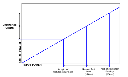
Figure 3: An amplifier operating within its linear region
Calibration
The IEC 61000-4-3 third edition requires that the extra power required for modulation be taken into consideration. Previously, calibration was performed at the nominal test level and modulation was added later and so the user may not have been aware that saturation was occurring. The latest standard requires the user to show that the amplifier will be operating linearly, at the nominal test level including the peak of the modulation envelope, which is 1.8 times the nominal test level.
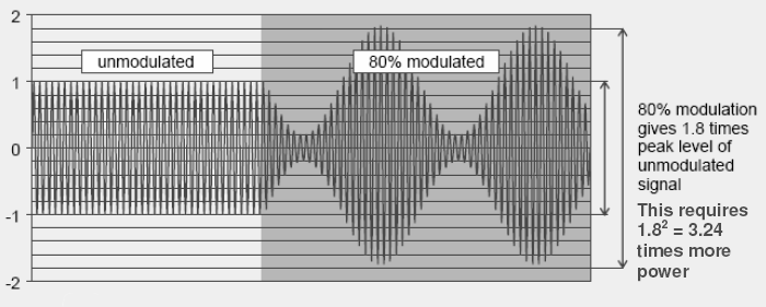
Diagram showing the relationship between the un-modulated test level and the modulated signal as described in IEC 6100-4-3
The new edition does not insist that the output modulation waveform is completely undistorted but requires that the amplifier be no more than 2dB into compression at the peak of the modulation envelope. To show this, the chamber must first be calibrated with the actual equipment that will be used for testing and at a level 1.8 times the specified test level (i.e. for 10V/m test the calibration is run at 18V/m). This calibration produces a list of powers required at each frequency to achieve at least 18V/m at one location in the uniform field with another 11 being in the range 0 to 6dB above this level (based on 16 point field uniformity, 75% of points must fall inside the 0 to 6dB range)
Subsequently, at each frequency the calibration power level is generated by the amplifier and then the signal generator level is reduced by 5.1dB. The power produced from the amplifier must fall by at least 3.1dB in order for the amplifier to be considered linear (meeting the 2dB linearity criteria, see Figure 4).
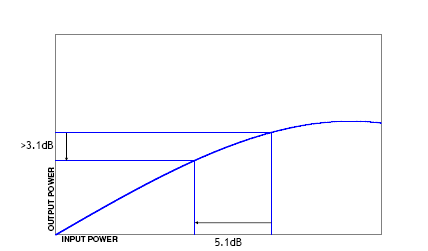
Figure 4: The amplifier’s output power must fall by at least 3.1dB for it to be considered linear
If this cannot be achieved, improvement to the system is required as it is necessary to operate the amplifier further down its gain curve. This may be accomplished in a number of ways: reducing the losses between the amplifier and antenna by the use of shorter or lower loss cables; using a higher gain antenna; improving the performance of the test chamber, or; using a higher power amplifier.
Test distance
The original issue of IEC 61000-4-3 defined the test distance as 3m from the uniform plane to the tip of a log periodic antenna or to the balun of a biconical antennal. This did not allow for the concept of the combination antenna such as the Bilog. Many users opted to set the distance to the phase centre of a Bilog (approximately half way along the Log Periodic section). This meant that the balun and hence the part of the antenna responsible for transmitting the lower frequencies was approximately 3.5 meters from the uniform plane.
The third edition of IEC 61000-4-3 defines the test distance for combination (Bilog) type antennae as 3 meters to the tip of the antenna (see Figure 5). This could increase the distance to the lower frequency radiating points of the antenna by up to 0.5 meters, which could add 1.16dB to the power required at the lower frequencies, or 30% more power.
 type antenna.png)
Figure 5: The specified test distance for combination (Bilog) type antenna
All amplifiers will produce harmonics of the input signal. The level of these harmonics is dependent on the design and quality of the amplifier and will worsen as the amplifier approaches saturation. The use of broadband, combination antennae leads to a potential problem. Since the gain of these antenna typically increases rapidly between 80MHz and 200MHz, harmonics produced by the amplifier in this frequency range have a disproportionate effect in the field.
Rather than define the harmonics from the amplifier, the third edition of IEC 61000-4-3 requires the user to show that the harmonics ‘in the field’ are at least 6dB down from the fundamental. As most test laboratories do not have frequency selective field measuring equipment, the standard allows the user to measure the harmonics from the amplifier at each frequency and then calculate the level in the field based on the performance of the antenna. The harmonics from the amplifier must be measured at the level required to create 1.8 times the target test level as established during the field uniformity calibration. Consequently it is important here again to ensure that the amplifier is not operating near the saturation level.
Figure 6 shows the gain versus frequency curve of a typical combination type antenna. Comparing the gain at 100MHz, 200MHz and 400MHz, it can be seen that it increases by around 6dB between 100MHz and 200MHz and by around 7dB between 100MHz and 400MHz. Harmonics would need to be at least 12dB and 13dB respectively below the carrier frequency (100MHz) to achieve a 6dB margin in the field. Most amplifier manufacturers specify harmonics of at least 20dB down from the fundamental but only in the linear region of the amplifier. Harmonics will increase once the amplifier starts to go into saturation.
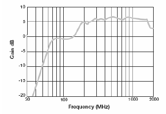
Figure 6: Gain vs Frequency curve of a typical combination antenna
The third edition of IEC61000-4-3 better defines the test conditions and clarifies some previous anomalies. The test distance for combination antennae is now better defined and the quality of the test field in terms of modulation shape and harmonic content is now specified. The purpose is to create more consistency and repeatability in testing but may result in some test facilities failing to meet the new requirements. Some improvements can be achieved by better antennae or cables but in some cases there will be no alternative but to increase the power available for the amplifier.
As with all aspects of RF EMC immunity testing, the amount of data required to confirm the field uniformity, amplifier linearity and harmonic performance, makes the use of automated test software essential. Teseq has just released version 4.00 of its Compliance 3 RF Immunity software which now includes all the necessary tools to allow a test laboratory to perform the field uniformity calibration at 1.8 times the nominal test level and then to determine and record the linearity and harmonics at the test level.
Why are harmonics in the field a problem?
This is explained in detail in Annex D of the standard and falls into three main areas:
Inaccuracy of measurement of the test level: Virtually all field measuring devices in common use in EMC test laboratories are broadband measuring devices, i.e. they have no frequency selectivity and therefore measure the total field present at all frequencies. If there is a significant harmonic content in the field, the measurement of the fundamental field strength will be incorrect. As there is no way of predicting if the various signals present will be added or subtracted (due to phase differences) there is no way to make any corrections for this error. It is therefore vital that the harmonic content of the field is kept to a minimum.
False failures in the EUT: It is possible that, when testing at a particular fundamental frequency, an EUT could have a susceptibility not at the fundamental but at the harmonic frequency. This would generate false failures at the fundamental frequency which could result in wasted time trying to design out the problem from the EUT.
When testing intentional receiver devices: Commonly when receiver devices are tested the test software is configured to skip the intended operating frequencies of the receiver. If however there are significant harmonics in the test field, high levels of the receiver’s operating frequency will be generated during the testing of the lower frequency range which could adversely affect the EUT.
Author profile: John Dearing is product manager for the Teseq range of RF broadband power amplifiers and Compliance 3 test software. Educated to degree level in Electronic and Electrical Engineering he went on to further study RF and microwave electronics while working on the deign and development of a range of rugged TWTs for the defence industry. Dearing later specialised in RF EMC test systems and has more than ten years experience in the supply and design of RF EMC test facilities.
Product Spotlight
APV1111GVY
Panasonic

Panasonic PhotoMOS® Photovoltaic MOSFET High-Power Drivers
| SKU: | |
|---|---|
| Stock: | 3490 |
| Cost: | $3.95 |
