
Actual measurement techniques for millimetre wave applications
Today’s most attractive millimetre wave applications lie on the so called E and V Bands. The first of these corresponds to a frequency range from 60GHz to 90GHz, at which Line Of Sight (LOS) transmission is mandatory due mainly to atmospheric attenuation effects. Indeed, many molecules from atmospheric gasses such as oxygen, water vapour or nitrogen can absorb energy at specific wavelengths within this band.
However, in the practice, the huge amount of spectrum available at these frequencies is driving the industry to move future technology over to this range. Similarly, V-Band operates from 40 to 75GHz and it is widely used to secure satellite communications. Victor Fernandez Wireless Specialist, Engineering & Technology Department, Anritsu EMEA explains.
There are three key applications being developed on these bands, namely mobile backhaul, automotive radar and Wi-Gig or 802.11ad. The first one relies on the fact that current Super Heterogeneous Networks are filled with multiple small cells which dramatically increase the need for transmission capacity in the backhaul.
The core network must handle huge amounts of data being transferred to each of the nodes in a specific area. Thus, basing these connections on millimetre wave radio links with bandwidths wider than 1GHz, we can fulfil the backhaul requirements for modern and future networks and still offer a lower cost solution compared to fibre optic. Mobile backhaul is the most important application together with automotive radar.
Appropriate measurement instruments
The 79GHz band will most probably become the standard frequency for FMCW (Frequency Modulated Continuous Wave) Radar technology. This technology can operate with signals of up to 4GHz bandwidth, which achieves the desired precision when detecting targets in automotive environments.
Finally, the so called Wi-Gig is a new flavour of WLAN 802.11 standard that has been developed for very high speed services such as uncompressed high definition TV (HDTV) and instantaneous music and image transmissions. This can be achieved by operating with 2GHz bandwidth at 60GHz.
Given the nature of the transmissions at these frequencies, appropriate measurement instruments will be required to enable all these technologies. These instruments will be mainly characterised by an outstanding dynamic range, to cope with highly attenuated signals, and the capability to measure ultra-wideband signals.
Different measurement solutions - harmonic mixer
Harmonic mixers are devices working in such a way that the finite local oscillator (LO) frequency (LO) taking part in the mixing process is leveraged by using harmonic components. The main advantage of using this kind of mixer is the simple and cost-effective solution it offers.
However, there are two main problems that arise from these systems. Firstly, the multiple harmonics that are used to leverage the LO signal introduce losses proportionally as soon as the frequency is increased. Thus, the dynamic range of the solution becomes very poor.
Secondly, the image response effect is very important here due to the multiple frequency components that are undesirably mixed in the process.
The image responses that have the largest impact on measurement results are displayed at an offset of twice the intermediate frequency (IF). As an example, if a signal coming from a FMCW radar with 4GHz bandwidth is measured by a Spectrum Analyser plus a harmonic mixer designed to work on 1.58GHz IF frequency, important tests such as frequency error, occupied bandwidth or transmit power cannot be measured because there will be an image response overlapping with the actual radar signal.
In some cases, this problem might be solved by image suppression methods. However, it is not effective in the case of FMCW modulation since the transmitted frequency is continuously changing.
Classic down converter configuration
The typical way to overcome the image response of solutions based on harmonic mixers is to use a classic down-converter set-up connected to the spectrum analyser (Figure 1). On one hand, due to the configurations used by fundamental mixers, which do not leverage the LO signal by using harmonics, an ideal IF frequency can be designed based on the frequency and bandwidth of the signal under test. Basically, a continuous wave signal generator combined with a multiplier will provide the necessary LO to down-convert the desired signal.
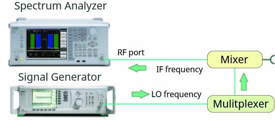
Figure 1: Classic down converter set-up connected to a spectrum analyser
On the other hand, a system needs to be built that combines several components such as mixers, local sources, multipliers, filters and gain amplifiers. Obviously, due to all these devices needing to be configured, calibrated and maintained while being used, it can be understood that down converter configurations are time consuming.
High performance fundamental mixers
Figure 2 shows the concept behind Anritsu’s High Performance Fundamental Mixers. The MA2808A and MA2806A, operating on E and V bands respectively, can be understood as integrated down converters, designed with in-built single purpose multipliers, low noise amplifiers, filters and high performance fundamental mixers based on waveguide technology. These devices offer a solution to the previous problems discussed - they have an good dynamic range, the image response happens very far away from the desired signal and they work with a single connection to the spectrum analyser.
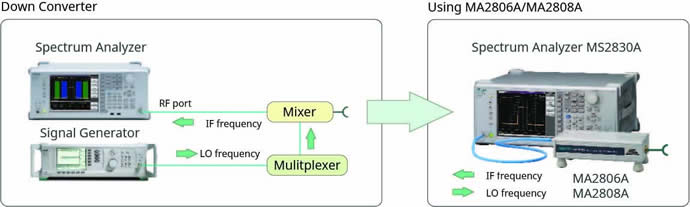
Figure 2: Instruments acting as integrated down converters
On one side, high performance fundamental mixers have two main benefits compared with harmonic mixers - better sensitivity or DANL, achieved thanks to the lower conversion losses, and better image response avoidance thanks to using a high IF frequency of 1.875GHz.
In addition to this, the internal mixer/filtering technology and the Polarisation Shift (PS) function enable the measurement of 4GHz bandwidth millimetre wave signals.
On the other side, high performance fundamental mixers have the following benefits compared to classical down converters - they allow a simpler configuration or connection to the spectrum analyser, conversion losses can be included simply from a USB memory via a single button operation, and offer a much better 1dB compression point performance than most commonly available down converters, which is in the order of 10dB improvement.
Without doubt, this compact test system can simplify the layout of design and manufacturing sites, and also reduce maintenance and calibration costs of measuring instruments.
Typical required measurements
Measurement of millimetre wave devices can be divided into two clearly differentiated parts - RF output characteristics (following ETSI EN 302 264-1 in Europe) and modulation or signal characteristics, which depends on the actual technology under interest. In the following subsections it is explained how the Anritsu millimetre wave solution stands out for each part.
In many cases, the TX power and spectrum emission mask of millimetre wave devices needs to be tested Over The Air (OTA) due to the nature of signals at these frequencies, which will suffer greatly from reflections, attenuation or material absorption. Thus, it is required that the test equipment is characterised by good sensitivity.
For example, if the testing antenna is 50cm away from the DUT, the free-space loss for 79GHz signal will be around 65dB. Since Maximum Radiated Average Power Spectral Density (EIRP) defined in ETSI EN 302 264-1 requests to measure <-40dBm/MHz, the requirement for test equipment will be approximately -142dBm/Hz at 79GHz considering a 23dBi testing antenna gain.
Generally, a typical harmonic mixer is characterised by a conversion loss of approximately 15dB to 20dB. When this is combined with a Spectrum Analyser, one can expect to have a Display Average Noise Level (DANL) between -135dBm/Hz to -140dBm/Hz, which will make it difficult to achieve the requirement mentioned above.
However, by combining the new MS2840A Spectrum Analyser with its noise floor performance and the MA2808A high performance fundamental mixer, the required sensitivity for TX Power and Spurious Emissions is widely achieved by at least 8dB.
Wideband modulation tests
To test the modulation quality of millimetre wave signals, the Phase Noise performance of the Spectrum Analyser is very important. For example, when testing FMCW Automotive Radar, it is required that Phase Noise characteristics and Frequency Linearity of the DUT are verified. When the time and frequency difference between transmitted and received signal is small and the Phase Noise performance of the Spectrum Analyser is poor, both signals cannot be separated because the received signal might be hidden into the phase noise of the transmitted signal, as shown in Figure 3.
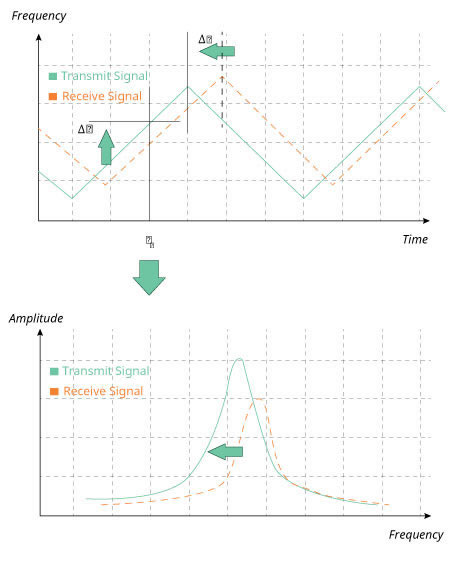 Figure 3: Testing FMCW Automotive Radar
Combining the MS2840A with the MA2808A, a close-in phase noise performance of <-100dBc (100kHz offset) and <-110 dBc/Hz (1 MHz offset) at 79GHz satisfies the requirement for automotive radar technology, which asks for at least -90dBc/Hz (100kHz offset) and -100dBc/Hz (1MHz offset) of phase noise performance.
Conclusions
With the upcoming 5G networks and the spread of ADAS, the demand for millimetre wave systems is growing. To test these ultra-wideband technologies spectrum analysers with external mixers must avoid the image response problem, must provide sufficient sensitivity for OTA testing and must have enough phase noise performance for modulation analysis. The combination of MS2830A/MS2840A Spectrum Analyser and MA2808A High Performance Waveguide Mixer is well suited to meet these needs.
Product Spotlight
APV1111GVY
Panasonic

Panasonic PhotoMOS® Photovoltaic MOSFET High-Power Drivers
| SKU: | |
|---|---|
| Stock: | 3490 |
| Cost: | $3.95 |
