
Radar technology puts complex demands on automotive supply chain
Vehicle construction is an innovation driver in Germany, and according to the report INNOVATIONEN IN DER DEUTSCHEN WIRTSCHAFT (Innovations in the German economy) of the Fraunhofer Institute and the Center for European Economic Research, €52.4 billion was invested in 2016 alone – with an upward trend. The focus is on autonomous driving, and new developments in this area mean continuous process changes, not just for automobile manufacturers. The entire automotive supply chain must adapt to new challenges.
Sensors – the heart of autonomous driving
Autonomous driving requires vast amounts of environmental information, information that is normally captured by the human eye and processed by the brain. The technical counterparts are sensors, which are key components in autonomous driving. Millions of automotive radars have been manufactured. They are standard equipment in high-end vehicles and are used by assistance systems to prevent accidents and increase driving comfort.
Radar sensors mainly use frequency modulated continuous wave (FMCW) signals. Due to the propagation delay and the Doppler frequency shift, the sensors can measure and resolve the range and radial velocity of multiple targets. Depending on the antenna array properties, it is also possible to measure and resolve the azimuth and even the elevation angle. During signal processing, the sensor electronics generates a target list containing the measured positions and velocities of the objects together with type information (pedestrian, car, etc.). This list is sent to the vehicle's electronic control unit (ECU), which uses it to make realtime decisions for vehicle maneuvers. The accuracy and reliability of this data is extremely important for the safety of the vehicle, its passengers and other road users.
Radome – a special challenge
For aesthetic reasons, radar systems are not installed openly on the vehicle. Instead, they are hidden behind brand emblems on the radiator grill and behind the front and rear plastic bumpers. These emblems and bumpers become radomes (radar domes). As radomes, they must be evaluated as RF components that affect the detection performance and accuracy of the radar hidden behind them. The RF transmission loss of the radome material attenuates the signal twice because the signal must pass through the material on the way to the target and on the way back. According to the laws of signal propagation, the power of the transmitted signal is inversely proportional to the square of the range r in each direction, which means it is reduced by a factor of 1/r4 over the round trip.
For example, if a 77GHz radar with 3W output power and a 25dBi antenna gain needs to detect a target with a radar cross section of 10m² and a minimum detectable signal of –90dBm, this would result in a maximum radar range of 109.4m – without the radome. If the two-way attenuation of the radome is 3dB, the range of the radar is reduced by 16 % to only 92.1m.
In addition to material attenuation, the reflectivity and uniformity of the radome material also play a significant role in radar performance. Reflections, for example from metallic particles in the paint, and RF mismatch of the base material produce interference signals within the radome, i.e. close to the sensor.
These interference signals are received and downconverted in the receiver chain, which reduces the radar’s detection sensitivity. Many vehicle manufacturers try to mitigate this effect by installing the radome at an angle so that the emitted radar signal is not reflected directly back into the receiver frontend.
This approach is subject to design constraints and does not eliminate the parasitic reflections that cause loss of RF energy. Another problem is that material inhomogeneities such as inclusions, density variations and the different material thicknesses in three-dimensional brand logos disturb the outgoing and incoming wavefront. It is distorted, leading to less accurate angle measurements. Radar sensor calibration can minimise this effect within certain limits, but cannot completely eliminate it since the calibrated radar may be mounted behind radomes from different manufacturers.
Calibration and validation – an opportunity for suppliers
To ensure radar reliability and safely implement assistance systems and autonomous driving concepts, it is essential to validate radomes and their properties. Subsequent correction of the materials used is extremely time-consuming and costly and therefore unacceptable for automobile manufacturers. As vehicles become increasingly independent, there is a need for high-quality radomes whose attenuation properties are not only minimal, but also constant and known in detail. Since automobile manufacturers want to keep testing as short as possible due to time constraints, suppliers who can provide already tested radomes with these properties and information have a clear competitive advantage.
In order to do this, suppliers need reliable and detailed product tests. Radome manufacturers typically use a reference radar (golden device) to test their products. In a stationary installation consisting of radar reflectors, differential measurements are performed at various distances and angles, both with and without the radome. The radome passes the test when the determined values remain within specified tolerances. As sensors and actuators take on more responsibility and the complexity of the radomes themselves increases, such selective tests are no longer sufficient.
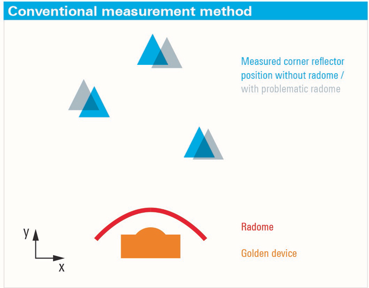
The test method of using only one reflector and the radar and radome placed on a turntable is more accurate. The measurement is repeated at various angles and the measurement results are compared to the angles indicated on the turntable. The more accurately the turntable can be positioned and the more angles that are tested, the more valid the result. However, this method takes a lot of time and is therefore not suitable for production tests.
Quality automotive radome tester – conclusive tests for practical use
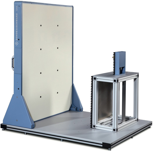
Rohde & Schwarz developed the R&S QAR quality automotive radome tester to provide a test procedure that delivers reliable data and is practical to use in terms of cost and speed. Instead of a golden device, it uses a large panel with several hundreds of transmit and receive antennas operating in the same frequency range as automobile radars. The antennas of the R&S QAR see what an automotive radar would see.
Thanks to the large aperture, it measures range, azimuth and elevation at a much higher resolution (in the millimetre range). This high resolution allows the reflectivity to be visualised as a type of X-ray image, enabling even non-experts to make an immediate quality assessment. In a second analysis step, quality parameters can be calculated from the image, which means previous production tests can be replaced by a simple pass/fail test. The use of many transmit and receive antennas makes it possible to test the entire radome in detail within a few seconds in one go (one-shot method) and eliminate time-consuming measurement sequences.
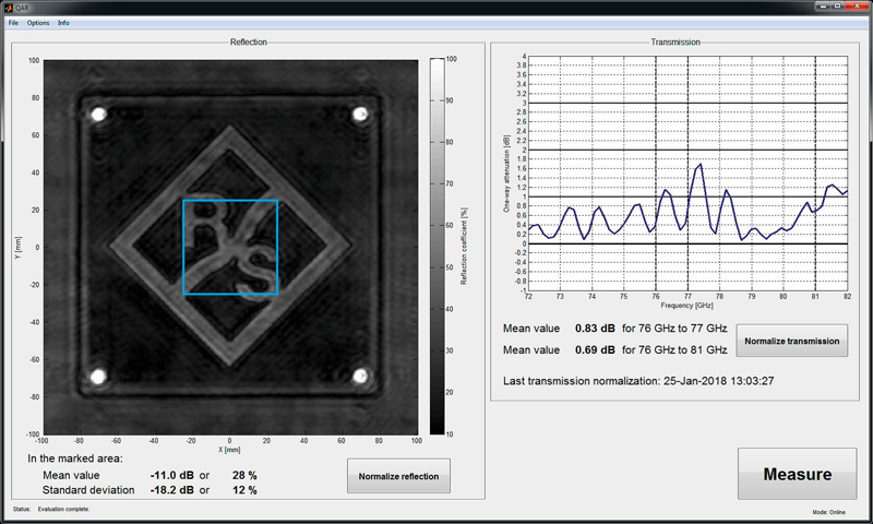
The R&S QAR allows measurements of both the spatially resolved reflectivity and the transmissivity of the DUT. The reflectivity measurement measures the energy reflected by the radome material. This is the loss that degrades its performance. Certain areas can have higher reflectivity for various reasons, e.g. material defects, air inclusions, unwanted interactions between different material layers or an excessive amount of certain material components. The measurement method delivers spatially resolved measurement results by coherently linking all reflected signals according to magnitude and phase. The visualisation of the results allows spontaneous, qualitative and reliable pass/fail evaluation as well as quantitative assessment of the DUT’s reflective behaviour.
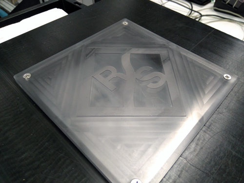
The high-resolution radar image above shows what a radar sensor covered by this demo radome would see. The brightness levels represent the reflectivity. The brighter an area, the more it reflects the radar signal. Metal objects show up as white (the screws in the four corners). The clearly visible contours of the logo indicate high reflectivity and a very non-uniform overall image.
The transmission measurement determines the frequency matching and attenuation of the radome material, which are the basis for its suitability. A calibrated transmission unit located behind the DUT sweeps over a selected frequency span. The receive array receives the signals, allowing precise assessment of the radome's transmission frequency response. The frequency response delivers detailed information about the RF matching of the DUT at the exact frequency band intended for radar operation. This information is independent of the actual signal waveform used by the radar unit and is therefore valid for all types of radars that can be installed behind the radome.
Summary
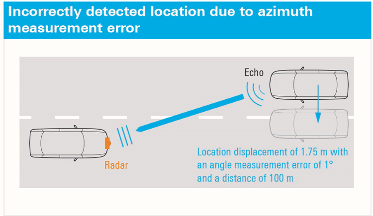
Autonomous driving requires radars that reliably, e.g. without errors, detect objects in the surrounding area. This depends both on the radar quality and the installation situation. Vehicle body parts used as radomes can degrade the signals to the point that objects are not detected at all or are detected in the wrong places.
Today, such parts not only serve their original purpose, they also need to have defined RF properties. Accurate and practical measurement methods are needed to verify these properties. The R&S QAR from Rohde & Schwarz offers an innovative, unique method that yields more detailed measurement results in considerably less time for both spatially resolved RF reflectivity and transmission measurements.
For automobile manufacturers, more tests mean greater expense and lower productivity, but for suppliers they represent opportunities. They can test the required parts themselves. This not only increases their own quality standards, it also allows them to increase customer loyalty by providing a specific additional service with the measurement data.
Article written by Andreas Reil and Dr. Steffen Heuel, Rohde & Schwarz.
Product Spotlight
APV1111GVY
Panasonic

Panasonic PhotoMOS® Photovoltaic MOSFET High-Power Drivers
| SKU: | |
|---|---|
| Stock: | 3490 |
| Cost: | $3.95 |
