
The efficient redundancy for power supplies
Maximilian Hülsebusch from PULS here reviews advances in reliable power system availability in the event of a short circuit. N+1 redundant power module connection guarantees reliable system availability even if a power supply fails. However, the common use of decoupling diodes in such modules causes a large voltage drop leading to high power losses generating heat.
After a complete design review PULS is now replacing these diodes with high efficiency MOSFETs. This redesign of redundant power modules also adds many other useful features for system designers.
In a redundant system, two or more power supplies are connected in parallel and decoupled by one or more redundancy modules. The module prevents short-circuiting of the bus voltage if a short-circuit occurs in the output side of a power supply.
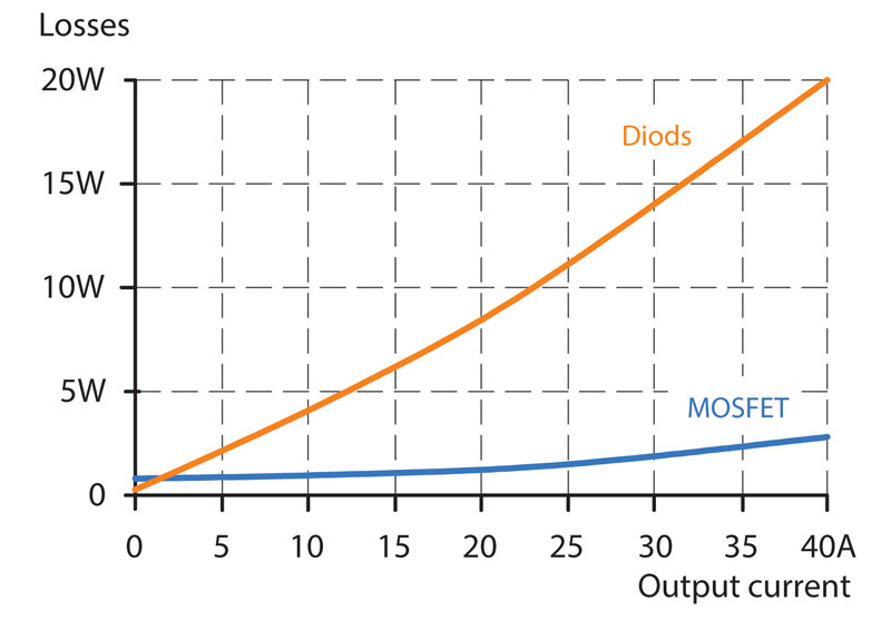
To achieve this, a diode or equivalent component is used for decoupling. One is sufficient for each power supply. The disadvantage of this method - diode decoupling - is significant power loss in the form of heat or example a load current of 40A creates approximately 20W of power losses (image 1).
This creates heavy thermally induced stress for the power electronics, which can only be reduced by means of large heat sinks. PULS engineers were not willing to accept this compromise. They carried out research to find out what end users specifically require in a redundancy system.
Ten criteria have emerged for optimal redundancy:
- Highest safety and availability
- Minimal power losses
- Ease of use
- Load-side return voltage immunity
- Short-circuit protection
- Parallel function: power distribution between power supplies
- Signal in case a power supply fails
- Inverse-polarity protected input
- Signal in case of error condition
- Hot swapping: Swapping without voltage interruptions
When analysing the results, it quickly became clear to the development team that standard epitaxial or Schottky diodes could not fulfil the need for minimal no-load losses. Therefore, a decoupling solution with MOSFETs was developed instead.
This technology reduces power losses. For instance, when using a MOSFET module, a load current of 40A will only produce power losses amounting up to 3W instead of 20W. However, points five and eight were a major challenge for the development team when designing the new MOSFET solution. This is because short circuits or inverse polarity in the power supplies could destroy the MOSFETs
Circuit design actuates MOSFET in case of short-circuit
If a short circuit occurs in the load or cabling, the power supply voltage fails and almost no useable voltage is present at the redundancy module input. However, the MOSFETs in the redundancy module must remain continuously actuated for the short circuit current to flow with low power losses.
Otherwise, this current is absorbed by the body diodes in the components. This increases power losses by 15 times and could eventually destroy the MOSFETs. This weak point of the components is overcome by a new circuit design that even in the case of a short circuit it takes advantage of the minimal residual voltage to actuate the MOSFETs properly (image 2).
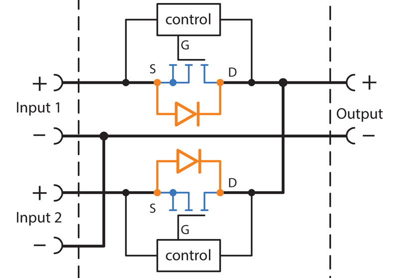
The circuit can be bypassed even in other critical situations, such as when the power supplies are connected to an existing short circuit or if the input voltage has been reverse-poled.
A voltage drop of just 50mV
With MOSFETs as a decoupling element, even voltage drops can be minimised. Diodes in standard redundancy modules cause a voltage drop of 500mV between the input and output.
Thanks to the MOSFET redundancy modules, this situation could be improved drastically. For instance, in a typical new redundancy module, the PULS YR80.241, the voltage drop at 40A output current is lower than 50mV between the input and output.
Uniform power distribution via parallel function
After implementing a MOSFET design even the parallel-use mode achieves better thermal balance, improving reliability and leading to an extended life time. In this process, the load current is divided equally between the individual power supplies.
There are two ways of integrating the parallel function in the system. It can be either integrated directly into the power supplies or into a stand-alone redundancy module. When integrated into the power supply, the output voltage is regulated in such way that it is around four percent higher at no load than it is at nominal load.
This results in an automatic current distribution between devices, as long as their no-load voltage is identical. If a power supply takes up more current, its voltage decreases automatically and a current symmetry is restored. This property ensures that there are no power losses in the current distribution.
When the parallel function is integrated into a redundancy module, the MOSFETs are used in linear mode. They generate a well dosed voltage drop in the channel with the higher voltage so that a current symmetry is achieved between the two channels, i.e. the power supplies. This method also enables power supplies without integrated parallel-use mode to be used in parallel.
PULS developers have worked intensively on the optimisation of both approaches. It is crucial for the parallel-use mode to always support the safety, availability and efficiency of the redundant system - both for classic 1+1 redundancy systems and for N+1 systems.
Hot swapping - replacement without voltage interruptions
An additional technical innovation implemented in the design of the PULS redundancy module YR40.245. Hot swapping is now available in this module for the first time. With 'hot swapping' allows the replacement of a power supply or a redundancy module while the system is running.
To enable this, the critical connections have plug connectors with short circuit protectionensuring it can be replaced without voltage interruptions. Redundancy is restored immediately after replacement. This is indispensable for critical systems, when even a temporary failure could mean significant security risks or serious economic losses.
Product Spotlight
APV1111GVY
Panasonic

Panasonic PhotoMOS® Photovoltaic MOSFET High-Power Drivers
| SKU: | |
|---|---|
| Stock: | 3490 |
| Cost: | $3.95 |
