
Relays in safety-related control systems
There are no fewer than seven ways for even a simple transistor to fail. This means that monitoring all the electronic components that may be defective in a safe electronic switching output calls for considerable effort and the use of such things as a clocked fail-safe unit and microcontrollers (Figure 1).
Author: Frank Liebusch, Business Development Manager, TE Industrial Technology
By comparison, diagnostics for a safe relay output involve nothing more than monitoring of the opening of contacts. Relays with forced contacts already have this diagnostic mechanism integrated; they return the result for further processing via an electrically isolated monitoring contact.
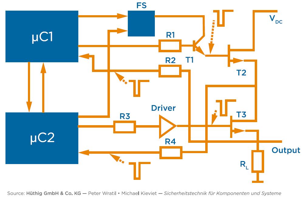
Figure 1
It is therefore no wonder that relays are the first choice of safety experts when simple circuitry is to be used to develop safe outputs, even for high voltages. Contact-based control outputs also exhibit greater inherent current-carrying capacity and resistance to peak voltages than electronic outputs; but when designing a safe output it is important to bear in mind that, over their lifetime, relays have an increasing failure rate, due to wear.
Types of relay faults
Figure 2 shows a 'bathtub curve' for a three-contact relay, clearly showing two exponential sections, corresponding to early faults and wear faults, and a central section with a more-or-less constant rate of random failures.
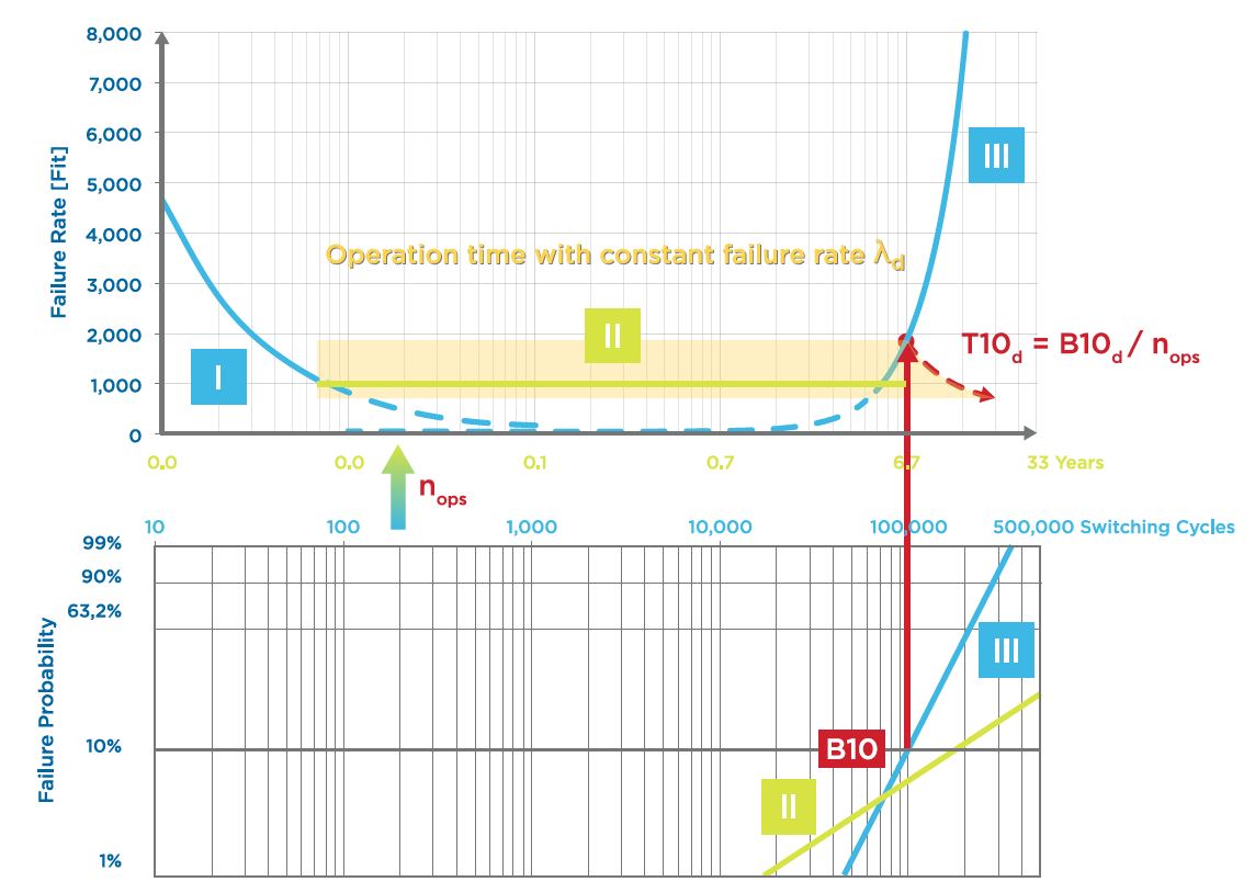
Figure 2
These random failures are not caused by wear and are therefore independent of the switching cycles. Like electronic components, relays exhibit faults that are evenly distributed over time. These include, for example, corrosion of contacts and other metal parts, environmentally-induced deformation of plastic parts, failures caused by faults in the manufacturing process, and tolerance violations.
The IEC EN 61709 standard (SN 29500) provides formulas that can be used to determine a constant failure rate on the basis of actual failures in the field. The exponential parts of the bathtub curve showing early failures and those caused by wear are left out of the recorded occurrences: only failures occurring after the first 5,000 switch cycles and up to at most 10% of the unit’s service life are considered. On this basis, the established failure rate of a 3-pole forced-contact relay (R-FC) in a typical application is 1,000FIT, which is entirely realistic. This predicts that after 20 years about 16% of the relays will have failed.
Failure rates obtained in accordance with IEC EN 61709 are used for calculations in which relays switch very rarely and the end of their useful life is most unlikely to be caused by switching wear.
Wear failures are known systematic faults that are caused by the contacts being eroded during switching operations. Their failure rate is therefore determined from the switching life of the relays at a specific load. This value is then scaled onto the time axis on the basis of the assumed switching frequency nop per hour for the application. Within the operating time T10d, the failure rate λd is regarded as constant.
![]() Formulas taken from EN ISO 13849, annex C4
Formulas taken from EN ISO 13849, annex C4
The service life B10, determined according to IEC 61810-2, is the number of switching cycles at which 10% of all the relays will have failed. Because safety calculations for safety circuits take into account only dangerous failures (non-opening contacts), B10d (where d = dangerous) can be higher than B10 by a factor of up to 10.
Relays in safety circuits
The probability of failure in a single relay is generally too high to protect against a risk. Relay circuits for various risk categories are known and can be verified as subsystems with quite simple components, as described in EN/IEC 62061, section 6.7.3.3. The basic subsystem architectures described in section 6.7.8 of this standard show how failure rates can gradually be reduced by redundancy (hardware fault tolerance) and diagnostics.
The tolerance for hardware faults is determined by subdividing them into safe and unsafe failures (safe failure fraction, SFF). For relays, this subdivision can be defined to be between safe non-closing failures and unsafe non-opening failures and determined by FMEA and field experience. This means that relays correspond to the type A subsystems defined in IEC 61508-2. It is generally assumed that the SFF of a non-monitored relay will reach a maximum of 95% if it is provided with an internal fuse rated at two-thirds of the contact current.
A hardware fault tolerance of 1 enables the effect of a single welded contact to be avoided by having two relays connected in series. In the event of a fault, the load will be isolated by the equivalent redundant relay.
The probability PFD(t) (Probability of Failure on Demand) of the simultaneous dangerous failure of two relays connected in series is significantly reduced, even without the need for diagnostics, but to a large extent any such failure will be due to faults with a common cause (CCD):
![]()
Such a common cause affects both relays equally, rendering the redundancy ineffective. Table F.1 in the EN/IEC 62061 standard provides criteria for determining the rate of failures with a common cause. Factors that have identical effects on redundant relays may be thermal, magnetic, electrical or mechanical, such as ambient temperatures or magnetic fields, and – particularly for polarised relays – overcurrents or mechanical overload.
The proportion of dangerous failures can be further reduced with proper diagnostics, since a certain percentage of the failures can be detected by monitoring (Figure 3). Table A.1 of the IEC 61508-2 standard describes requirement levels for detecting the causes of failures. Here, forced contacts offer the highest possible diagnostic coverage, namely 99%.
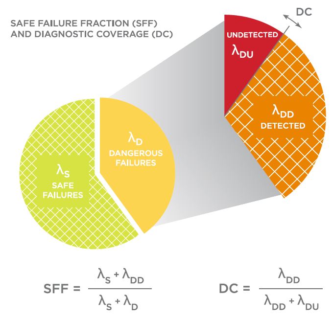
Figure 3
Relays with Forced Contacts (R-FCs)
R-FCs guarantee that a second antivalent contact is closed only when the contact gap is wider than 0.5mm. Apart from this, R-FCs do not provide any more safety than an elementary relay; indeed, like all relays, they can fail due to faults or because they come to the end of their useful life. However, evaluating signals from the monitoring contact enables automatic diagnostics for each switching cycle; in this case the safety circuit can prevent a restart.
The IEC 61810-3 (EN 50205) standard describes how to design and test forced relays in such a way that the antivalence of the normally open and normally closed contacts is not lost, even in the event of a fault. Here, the contacts are connected mechanically via an actuator and sufficiently dimensioned that they will not break. In situations where such oversizing is not possible, such as at the bending points of springs, potential fragments are secured so that they do not short-circuit the antivalent contact.
Like Electromechanical Relays (EMRs), the dimensions of relays with forced contacts need to be chosen to suit the control circuit, the contact circuit and the ambient conditions. In this respect, relays with forced contacts are no different from any other EMRs. When dimensioning, for example, the drive voltage, or determining the expected service life or impact resistance, extensive literature and application notes can be referred to.
A number of specific questions have emerged that apply especially to R-FCs, relating to typical fields of use or the avoidance of common-cause failures.
Determining electrical and mechanical parameters
For a compact arrangement of relay-operated safety circuits, it is usual to employ 'safety relay modules' contained in narrow housings that are designed for mounting on a DIN-rail. The maximum ambient temperature for relays given in IEC 61810-1 cannot be used here, since the distances to the housing wall and the proximity of other heat sources make it impossible to determine in a standardised manner the ambient temperature in the vicinity of the relays. It is therefore necessary to measure the temperatures of the relays directly under worst-case conditions.
This is done with tightly packed relay modules, using the maximum supply voltage with as many as possible of the components activated; the temperature is then measured directly at the hotspots on the relay surface, while the coil temperatures are determined from the resistance of the wire. Limiting values for temperature load are provided by the relay manufacturer, and the application notes will help in carrying out these measurements.
In addition to the functional aspect when configuring the controller, the temperature also plays a safety-critical role that must not be overlooked. In other words, what happens if the temperature goes outside the range specified by the manufacturer? What could give rise to such a deviation and could the same cause possibly affect redundant relays at the same time? Since manufacturers do not test the effect of temperature deviations outside the specified range, we must assume that a critical failure would result. For this reason the device’s safety assessment should include compliance with the stipulated temperature range.
Another range specified by the manufacturer is impact and vibration resistance. If components, PCBs or devices fall onto a solid surface, they can be exposed to loads higher than the permissible maximum. Damage is often not visible from the outside, but parts may become misaligned or may splinter, thus reducing the contact distance or even jamming the relay completely. Suitable quality management must therefore be in place, with appropriate measures being taken to detect excessive impacts and ensure that mechanical loads encountered during processing, transport and operation are all within the specified range.
Conclusion and outlook
Relays with forced contacts adapted to safety applications in elevators, railway engineering, mechanical engineering and automation are available in versions with from two to ten contacts. Users expect both further miniaturisation and cost-effective solutions that can be used to cover slight risks. Integrated sensors could not only promote miniaturisation and reliability, but could also enable additional functions.
The normatively required delimitation of a relay’s application range prior to the occurrence of hazardous wear failures (B10d) is now carried out using assumed values for the expected operating time, contact load and switching frequency.
From the user’s point of view, however, it would certainly be useful to be able to recognise an increase in the relay’s tendency to weld shut or jam under field conditions.
In summary, particularly where components are understood as subsystems and different technologies come together, we can envisage additional possible applications opening up for relays in the field of safety technology. Standardisation for functional safety leaves plenty of room for new solutions.
Product Spotlight
APV1111GVY
Panasonic

Panasonic PhotoMOS® Photovoltaic MOSFET High-Power Drivers
| SKU: | |
|---|---|
| Stock: | 3490 |
| Cost: | $3.95 |
