
Induction heating technology in small home appliances
Induction heating brings precise and even heat control to cooking. It offers many benefits over conventional heating elements. Giuseppe de Falco, senior technical marketing engineer, Infineon Technologies, looks at the physics and the electronic technology used in many of our kitchen cooking appliances.
Home cooking is enjoying a resurgence of interest, not least because the Covid-19 pandemic has kept everyone indoors with time on their hands and no restaurants or fast-food outlets open. TV programmes and blogs are introducing all levels of cook to healthier and more exciting dishes. There is also increasing awareness of the environmental impact of plastic-packed, pre-prepared food with its carbon-footprint overhead. Furthermore, modern kitchen gadgets with their style and functionality are appealing to the digital generation especially when the temptations of better tasting food with easier appliance cleaning and lower energy costs are combined with the appeal of technology.
Induction heating is now a key element in many small home appliances such as rice cookers, fryers and even milk-frothers, giving the benefits of precise and even heating control, speed of response and better energy efficiency when compared to conventional electric heating elements. Analyst Allied Market Research forecast the induction cooker top market will be worth over $13.5B by 2022, growing at nearly 6% CAGR.
Induction cooking starter
The induction cooker design starts with a transformer, similar to that used in many products converting mains AC voltage to a lower value, but without the secondary coil and bringing metal close to the primary winding. When the primary coil is energised, the transformer sees the adjacent metal as a shorted secondary turn and induces eddy currents to flow within it. If the metal has resistance, Joule heating (see below) results from I2R losses. If the metal is the bottom of a pan or lining of a table-top cooker, this is the basics of an induction cooker (Figure 1).
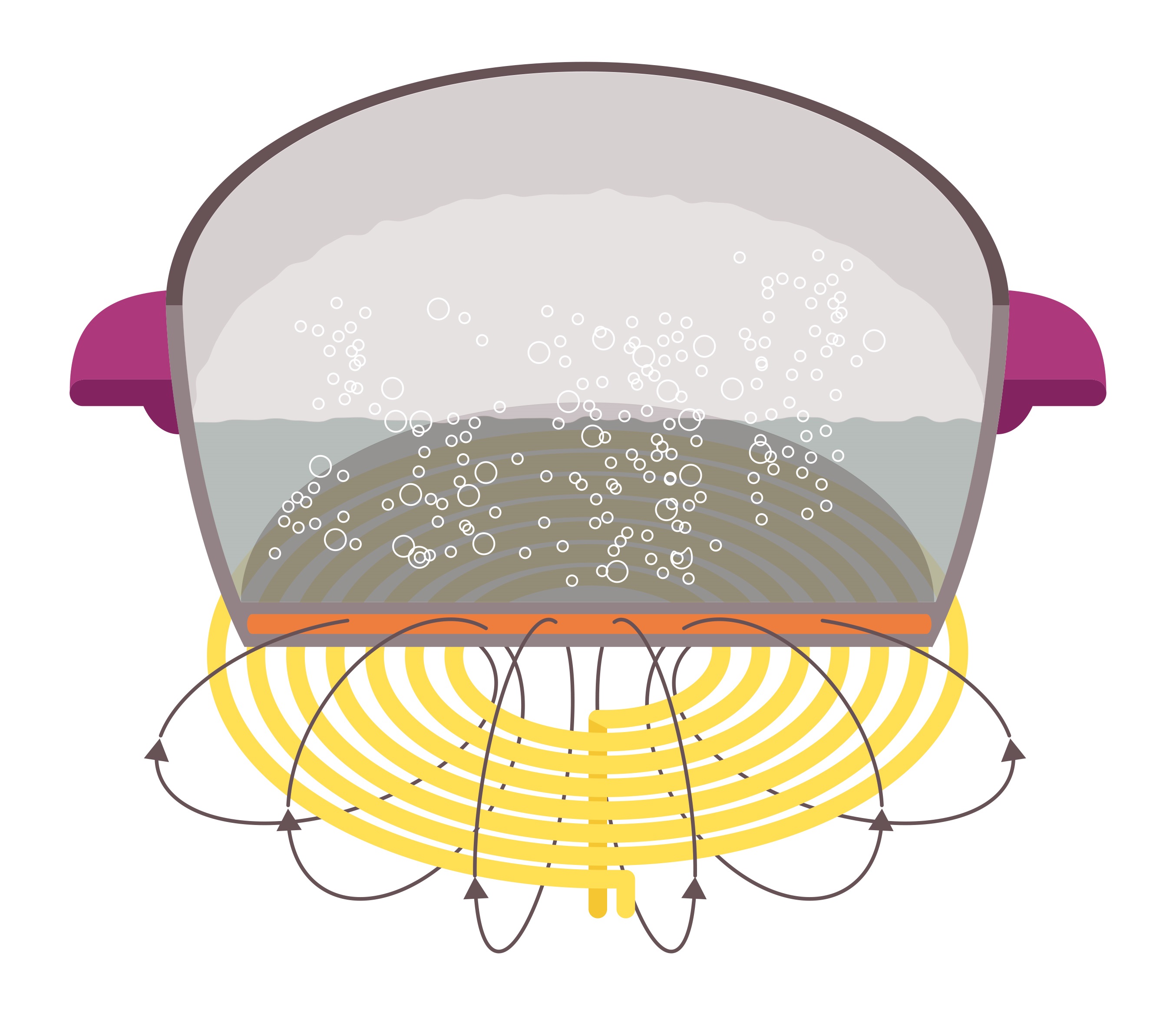 Figure 1: Inductive hobs develop heat in the cooking vessel through Joule heating
Copper and aluminium have very low resistivity so do not heat up much, although if the AC frequency is high, a skin effect comes into play which tends to force current to flow along the surface of the metal rather than its bulk. This reduces the electrical conduction area, increasing resistance and the heating effect. If the metal has magnetic permeability, such as iron or steel, its ferro-magnetic crystalline structure comprises microscopic magnetic domains. These are forced to be in alternating alignment directions thanks to the applied magnetic field from the primary coil.
The domains react with what appears as friction to this effect, taking energy to rotate them, which in turn generates heat. This process, known as Joule heating, provides the rise in temperature needed for cooking. The transformer primary AC could be 50/60Hz directly from the mains but this would result in an unfeasibly large product and a very small ‘skin’. Instead, higher frequencies are used in the range of 25kHz to 75kHz, which reduces overall size. The transformer primary, the induction coil, has fewer turns at higher frequency and hence less resistive loss but the same skin effect comes into play. A typical coil is wound with litz wire that is made up of parallel strands of thin, insulated wire, each with a diameter smaller than the depth of the skin effect to reduce the skin effect losses.
A recipe for success
Generating high frequency AC for the induction coil can be achieved in a number of ways but the preferred solution for the best combination of efficiency and cost for smaller appliances up to 2.1 kW is to use a single-ended parallel resonance (SEPR) converter (Figure 2).
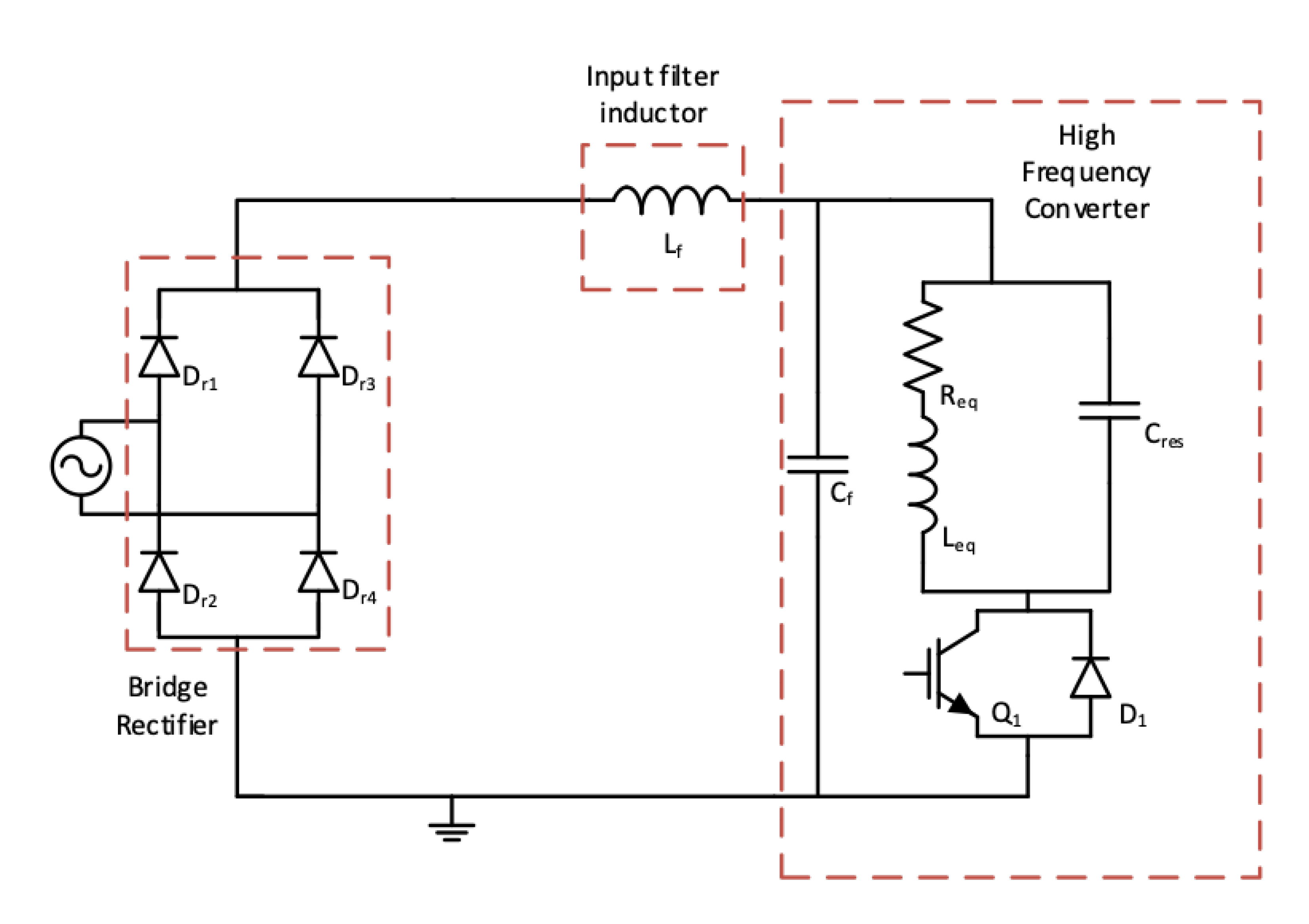 Figure 2: The SEPR design is typically used in induction heating applications of up to 2.1kW
In this illustration, device Q1 is an IGBT, switched by a controller at variable frequency, perhaps down to 20kHz at full load. Leq is the induction coil. At steady-state, Q1 switches on with zero Volts at its collector and current flows from the rectified mains through Leq, rising linearly. At a controlled current level, Q1 turns off and the current circulates through Cres causing the collector voltage to peak then fall at the natural resonant frequency of Leq and Cres – the AC needed for the induction coil primary. As the voltage falls below zero, D1 conducts and current circulates through Cf. At this point, Q1 is switched on again and the cycle repeats. Power is controlled by setting the IGBT switch-off current Ipk, effectively defining the energy available in Leq according to energy = 0.5LeqIpk2.
The circuit is efficient, with zero-voltage switching at turn-on but the IGBT does see a voltage up to about twice the peak voltage of the mains. Turn-off losses are also low as the rise of the collector voltage is slow, limited by the resonant capacitor. Note that no bulk or reservoir capacitor is present and Cf is quite small, so power factor is good and does not require correction to meet EMC standards. However, a high frequency mains filter would normally be included to comply with statutory conducted interference limits.
The circuit is relatively simple and does have some limitations. Voltage stresses on Q1 are high and there is no bulk capacitor to attenuate mains surges, both of which add to the stress. Transient conditions such as on start-up and when, in the case of a hob, a saucepan is removed, can cause current spikes and loss of zero-voltage switching which can be damaging to Q1. The IGBT therefore needs to be specified for the application and protection mechanisms implemented.
The IGBT and its control are key ingredients
The voltage rating of the IGBT needs to be high, above 1200V, to allow for the peak resonant swing and transients at high AC mains. Current rating should have some margin for the transient conditions and saturation voltage VCE(on) should be as low as possible to minimise conduction losses. Turn-off losses are low because of the slow dV/dt of the rising collector voltage but IGBT off-state tail current should be controlled so that dissipation does not build up. Tail current and VCE(on) are a trade-off, so a good compromise has to be set for best efficiency to meet consumer and energy-rating demands. For transient conditions, ideally, IGBT current, voltage and temperature should be monitored and limited.
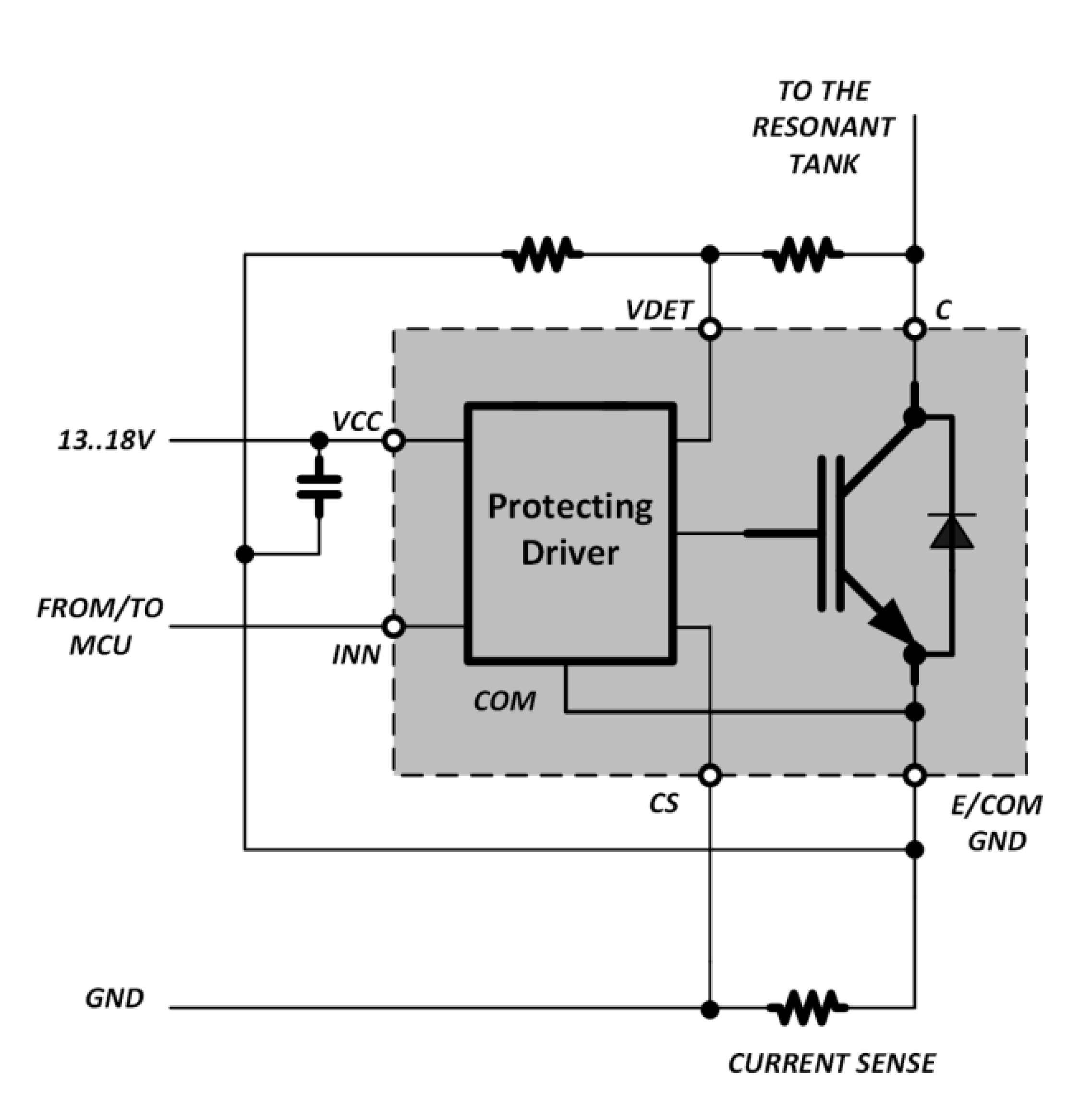
Figure 3: The TrenchStop F Series IGBT includes an integrated protecting driver
The TrenchStop F-Series protected IGBT RC-H5 is specifically designed for induction cooking applications, which are based on a SERP converter (figure 3).
It is a 1,350V 20A rated device in a TO-247 six-pin package tailored for SEPR induction-heating applications up to about 2.2kW. Switching losses are claimed to be best-in-class and a parallel diode is included with the necessary low forward voltage drop. It has many in-built protection functions, including a cycle-by-cycle current limit, which also serves to set the maximum LC resonant energy and hence peak voltage. This is monitored at the VDET pin with three different thresholds using a scaled replica of the collector-to-emitter voltage via a voltage divider formed by two resistors.
Initially the IGBT is immediately switched on for 5µs, clamping the over-voltage. After this time, the IGBT turns off and, if the energy in the inductor is still present, the voltage increases even further until the next threshold is passed. At this point, the IGBT turns on again but stays on until VDET falls below the first threshold value. With this two-step process, dissipation is significantly less than continuous clamping with transient over-voltages. The third and lowest threshold has the opposite effect of inhibiting normal IGBT turn-on if the voltage is too high. The required resistor values for the voltage divider can be determined as shown in figure 4. A bypass capacitor should also be considered here as a stable voltage is required for reliable operation.
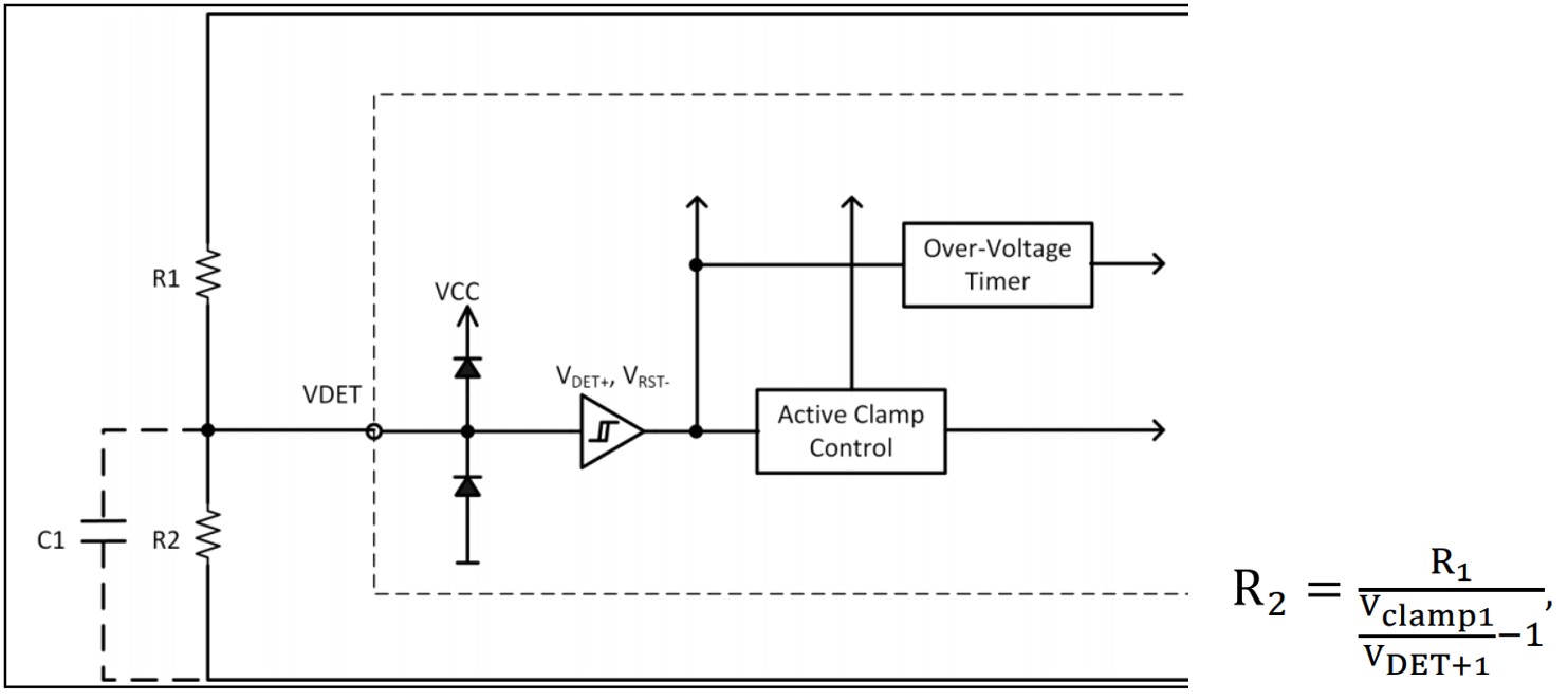
Figure 4: A resistor divider delivers a scaled version of the collector-to-emitter voltage
Gate drive turn-on current is in two steps, initially a lower value, to reduce dV/dt and dI/dt, reducing the spike of collector current due to charging of the resonant capacitor, then a higher gate current is set to ensure full IGBT saturation and lowest conduction losses. Temperature is also monitored with a warning signalled via the multi-functional INN pin if the die exceeds 75°C and with full shutdown if it exceeds 150°C. The INN pin is actively pulled low to drive the IGBT on, but in the off state, the external circuit goes to high impedance and the IGBT signalling then controls the pin with different voltage levels, indicating normal or over-temperature conditions (Figure 5).
Appliances take the heat
Induction heating design for visually appealing, small appliances is now simpler than ever. Integrated IGBT and driver solutions provide high efficiency, while keeping costs and size down. Their comprehensive protection mechanisms and generous ratings ensure reliable operation in the heat of any kitchen.
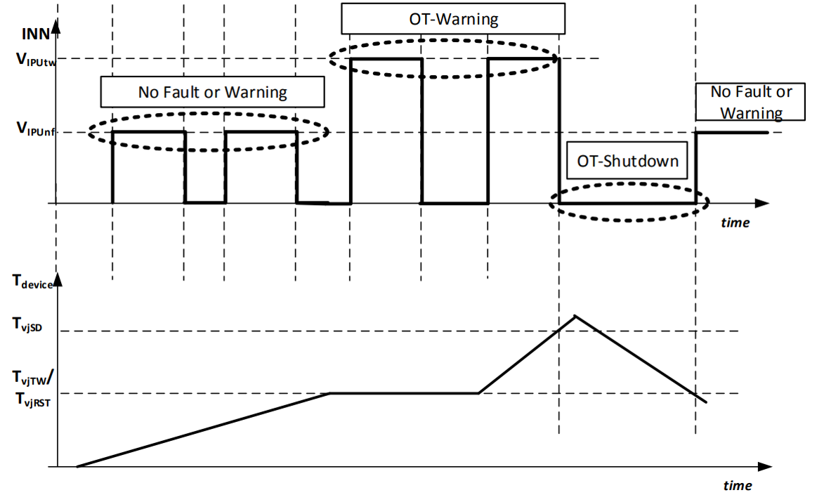
Figure 5: The INN pin provides advance warning of potential over-heating

Featured products
MAX17793
Analog Devices Inc.
3V to 80V, 3A, High-Efficiency, Synchronous Step-Down DC-DC Converter
| SKU: | MAX17793 |
|---|---|
| Stock: | 9316 |
| Cost: | $3.64 |
MAX22516
Analog Devices Inc.
IO-Link Data Link Controller with Transceiver and Integrated DC-DC
| SKU: | MAX22516 |
|---|---|
| Stock: | 8000 |
| Cost: | $5.42 |
Product Spotlight
102991834
BeagleBoard

Single Board Computer (SBC), BeagleY-AI
AM67A BeagleY-AI Jacinto 7 AR...
| SKU: | 2820-102991834-ND |
|---|---|
| Stock: | 183 |
| Cost: | $56.24 |
SC1110
Raspberry Pi
Raspberry Pi 5 2GB
The Raspberry Pi 5 2GB model represents a leap for...
| SKU: | 2648-SC1110-ND |
|---|---|
| Stock: | 185 |
| Cost: | $38.33 |
AKX00069
Arduino
Arduino Plug and Make Kit
The Arduino Plug and Make Kit features the ...
| SKU: | 1050-AKX00069-ND |
|---|---|
| Stock: | 945 |
| Cost: | $66.97 |
300361-0011
Molex
MX150 Mid-Voltage MatSealed Female Connector Assembly, Dual Row, 20 Circ...
| SKU: | |
|---|---|
| Stock: | 280 |
| Cost: | $2.51 |