
Antenna technology for the IoT
Connecting devices is key for IoT and M2M applications. Wireless links are a fundamental way of making these connections, allowing devices to be configured and controlled around the world. But this global capability introduces a wide range of choices that impact on the power consumption and performance of the whole system.
By Marco Enge, Senior Product Manager, Interconnect EMEA, Avnet Abacus.
There are many different ways of connecting up devices and they all have their own engineering trade-offs, particularly in the antenna design. The unlicensed sub-GHz and 2.4GHz bands used for protocols such as ZigBee and WiFi are available all around the world, but require access points. Cellular technologies such as GSM, GPRS and EDGE, 3G and LTE are available in many more locations but a broad range of frequencies needs to be supported, which impacts on the size and power of a wireless node. At the same time satellite tracking using GNSS systems such as GPS have even higher power and antenna requirements, while at the other end of the scale, NFC can provide a small, low power, low cost tag for the simplest tracking technology.
There are also different antenna architectures, ranging from a simple single channel half duplex link to a full MIMO high performance RFFE that can offer higher data rates and higher link budgets by reducing the effects of obstructions, reflections and EMI.
All of this makes the design of the antenna system increasingly complex, leading to key design choices for a wireless node. These antennas can be a limiting factor in the design of the system, as doubling the power output of the transmitter only increases signal strength at the receiver by 3dB and doubles power used by a battery. The choice of antenna also allows a more effective system, as it can optimise SNR and operating range for a given power level and can extend operating life between battery charges or changes.
These antennas can be implemented as tracks in or on a PCB as stubs or even fractals, as surface mount chip components, externally mounted fingers or a range of form factors, often depending on the frequency range and the type of application and all having an impact on the SNR and the power consumption.
ISM
There are three main global unlicensed bands where wireless devices can operate without restriction. In the 2.4GHz band you have 802.11b, g and n WiFi, Bluetooth, ZigBee and other wireless protocols such as Wireless HART. These all require gateways or access points to link a node to a network. 802.11n operates with MIMO antennas and can provide from 54 to 600Mb/s data rates as a result. 802.11a operates at the higher, less congested 5GHz band, while the sub-GHz ISM bands are crowded with many different kinds of implementations and proprietary protocols. Operating at 868MHz in Europe and 915MHz in the US, these have longer range and more penetration and simpler antenna designs for simple megabit links.
Because of the popularity of WiFi around the world there is a wide range of antenna solutions for the 2.4 and 5GHz bands. A dual-band dipole (2.4 and 5GHz) antenna shown in figure 1 doesn’t need a ground plane and is mounted by peeling off its backing tape and sticking it to a convenient surface. It is 70% efficient at 5GHz and 80% efficient at 2.4GHz.
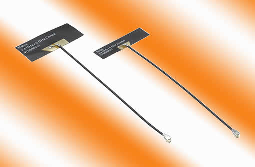
Figure 1 - A peel-and-stick dual-band 2.4 and 5GHz dipole from Molex is simple to apply to a mounting surface
There are also peel-and-stick, dual-band antennas for the 868 and 915MHz ISM bands, which can be up to 75% smaller than conventional antennas. And, as balanced devices, they’re independent of any ground plane with efficiencies of 50 and 67% at 868 and 915MHz, respectively.
There are different requirements for the wireless nodes – which have to be small and low power – and the access points, which are powered. This allows larger antennas to be used with the access points, providing peak gain between +2.4 and +4.9dBi and handling up to 3W of power.
ISM frequency bands:
- 433.05 to 434.76MHz (US)
- 868 to 870MHz (Europe)
- 902 to 908MHz (US)
- IEEE802.11b, g and n: 2400 to 2500MHz
- IEEE802.11a: 5000MHz
- Bluetooth: 2400 to 2483.5MHz
- WiMax: 2300 to 2700 & 3300 to 3800MHz
Cellular
Using cellular networks for M2M and IoT connections has the advantage of not requiring an access point or gateway device allowing scaling more effectively across large areas. However these have some key considerations for the antenna system. If a system is to be used around the world it may need a wide range of frequencies, which will be different depending on the data requirements of the application and on the typical use case.
Traditional GSM links can be from 850 to 1900MHz, requiring different antenna designs and delivering a few megabits of data. However the indoor performance of the 900MHz version of GSM is significantly better than the 1800MHz versions as a result of less absorption. Higher frequencies that support higher data rates have even more absorption and so are less suitable for indoor use without repeaters.
Current 3G technology at 2100MHz provides up to 100Mb/s downloads via HSDPA, although this can be an expensive way of providing a link. Although LTE can provide up to 300Mb/s peak data rates for downloads (and, more importantly for M2M applications, 75Mb/s uploads) it marks a move to packet-based networks. This means that although the frequency bands are more complex and higher, up to 2600MHz, the power consumption for low data rate applications could be lower. This will come from a quicker set up and break down, sending just the required packets rather than having to set up a circuit, which consumes more power.
This again has an impact on the antenna design. Having separate antennas for the different frequencies can hit performance and size, especially if multiple antenna switches are needed to change to a desired band. Inefficient switches can reduce the link performance that an antenna designer has worked hard to optimise.
However, these issues are handled regularly by manufacturers, as, unlike the ISM bands, any M2M module has to be certified for use on the telecoms networks. This makes the module easy to integrate into an existing design with the requisite SIM module. As these modules are often developed to the specification of a network operator the antenna design covers only those frequencies that the operator will support in various geographies.
For mobile applications, these modules also include the GNSS satellite antenna and receiver. This can be used to provide the location of a mobile device to the cellular module to transmit to the network and so locate the item.
Cellular network frequency bands
- GSM, CDMA and WCDMA (850/900/1800/1900MHz)
- UMTS/3G (2100MHz)
- LTE 4G - North America: 700, 750, 800, 850, 1900, 1700/2100, 2500 and 2600MHz (bands 2, 4, 7, 12, 13, 17, 25, 26, 41); Europe: 700, 800, 900, 1800, 2600MHz (bands 3, 7, 20); Asia: 1800 and 2600MHz (bands 1, 3, 5, 7, 8, 11, 13, 40); Oceania: 1800 and 2300MHz (bands 3, 40)
- GPS: 1565 to 1585MHz
NFC
NFC is at the other end of the complexity spectrum for M2M and IoT designs. The simple designs operate at 13.56MHz over distances of up to 10cm, coupling a passive antenna to provide the power for a short two-way link. These simple loop inductors are scanned to provide their data, and used for credentials storage and exchange, accessing and controlling data and wirelessly connecting to tags. Inductor values are typically between 0.5 and 1µH and with a suitable matching network they present a 50 to 80Ω impedance match.
For mobile applications, one of the key challenges is to make the NFC antenna as thin as possible and there is a further constraint as the casing of the device often acts as a shield.
Another limiting factor will often be the bandwidth needed for data transmission. The higher the permissible Q-factor, the stronger the radiation for a given power level and the more effective the link. This is more important when NFC tags on equipment are read automatically to confirm their location and contents.
The NFC antenna in figure 2 is a thin, flexible antenna measuring 25x25x0.005mm. As a bare 0.9µH coil without a matching network it has a resistance of 1.55Ω, a Q-Factor of 57 and is self-resonant at 100MHz. A matching network with a 15.4MHz low pass filter and a matched Q-factor between 5 and 30 provide the optimum performance for the coil.
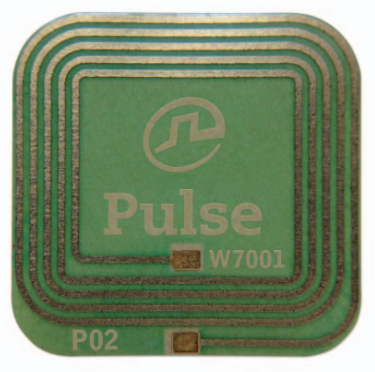
Figure 2 - Pulse Electronics' W7001 is a low-cost, very thin and flexible NFC antenna
Conclusion
The antenna forms a vital part of any wireless node design for IoT and M2M applications and yet it is little understood. Optimising the design of the antenna for the frequency band or bands that will be required by the node is not trivial but it can provide significant advantages in reducing the power consumption and boosting the battery life. The way the antenna can be optimised depends on the frequency bands and the types of wireless link – NFC is very different from cellular links yet both can deliver a global capability. The popularity of the ISM bands continues to reduce costs, while the increasing use of WiFi and Bluetooth around the world adds other considerations to the design of a platform.
 |
Author Bio: Marco Enge is responsible for product marketing and strategy, specialising in interconnect solutions. He has over 20 years experience in electronics marketing having begun his career with Siemens, and subsequently occupied roles with Vogt Electronic and Sun Microsystems before joining Avnet Abacus in 2006. |
Product Spotlight
APV1111GVY
Panasonic

Panasonic PhotoMOS® Photovoltaic MOSFET High-Power Drivers
| SKU: | |
|---|---|
| Stock: | 3490 |
| Cost: | $3.95 |
