
Next-generation router and switches demand flexible DC/DC controllers
Increasing complexity in routers and switches demand efficient power supplies in a small form factor. Bruce Haug, Linear Technology, explains how a multi-phase, step-down controller plays a part in meeting these challenges
System designers often have variations of a base architecture, allowing them to offer high, medium and low-end systems, each with different feature sets. Examples of device types that can be added, removed or sized according to system needs are CAM (content-addressable memory), TCAM (ternary CAM), ASICs (application specific integrated circuits), full custom silicon and FPGAs (field-programmable gate arrays).
A CAM is often described as the opposite of RAM. To retrieve data on RAM, the OS must provide the memory address where the data is stored. Data stored on CAM can be accessed by performing a query for the content itself, and the memory retrieves the addresses where that data can be found. Due to its parallel nature, CAM is much faster than RAM, but it consumes more power and generates more heat. CAMs are expensive, so are not normally found in PCs. Even router vendors will sometimes skimp, opting to implement advanced software-based searching algorithms. CAMs are found in network processing devices, including Intel IXP cards, routers or switches. The most commonly implemented CAMs are binary CAMs. They search only for ones and zeros. Any switch capable of forwarding Ethernet frames at gigabit line-speed is using CAMs for look-ups. If using RAM, the OS would have to remember the address where everything was stored. With CAMs, the OS can find what it needs in a single operation.
Memory types
A TCAM searches its entire contents in a single clock cycle. Ternary refers to the memory's ability to store and query data using three inputs: 0, 1 and X. The X input, which is often referred to as a “don’t care” or “wildcard” state, enables TCAM to perform broader searches based on pattern matching, as opposed to binary CAM, which performs exact-match searches using only 0s and 1s. Routers can store their entire routing table in these TCAMs, allowing for very quick look-ups. TCAM increases look-up speed, packet classification, packet forwarding, but it requires more power than a CAM. Both CAMs and TCAMs require accurate set points and have tight voltage transient requirements that are very challenging for power designers.
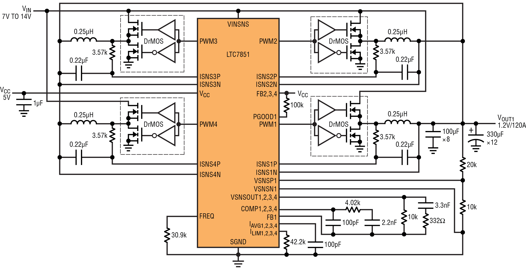
Figure 1: LTC7851 simplified schematic delivering a single 1.2V/120A output
An ASIC can be used in routers and switches, and is customised for a particular, rather than for general-purpose, use. It may often include entire microprocessors, memory blocks including ROM, RAM, EEPROM, flash memory and other large building blocks. Such an ASIC is often termed a system on chip (SoC) and these can require hundreds of amps with voltages in the range of 0.8 to 1.2V. As with TCAM and CAM, set point accuracy and transient response is critical to the overall performance. Size and current control are also key requirements for the power designer.
In specialised systems, FPGAs allow users to tailor microprocessors to meet individual needs. These devices have several voltage inputs and the core power can require currents in excess of 100A.
Scalability
The amount of CAMs and TCAMs allocated to a particular router depends on how the networking company positions their low, medium or high-end routers. The more expensive routers will normally have sufficient CAMs and TCAMs to support the highest speeds, fastest look-ups and highest throughputs. Some customers cannot justify the cost of a high-end router purchase, so there is a need to offer multiple platforms with different levels of functionality.
It would be convenient if there was a DC/DC converter that can be used across different power levels and number of outputs to support multiple platforms. Existing solutions usually provide a multi-phase design, but with only one or two outputs. If there are more than two high current loads, users need to use multiple controllers, which increases size, design complexity and cost. Some solutions require a specialised power train devices that are not compatible with standard DrMOS or power block devices.
The LTC7851/-1 controller, from Linear Technology operates across multiple platforms that require both high current outputs and dense multiple output PoL solutions. The multi-phase, synchronous voltage mode, step-down controller allows users to choose from one, two, three or four outputs and can deliver up to 40A/output depending on the choice of external components. All four phases can be combined to provide 160A for a core supply as an example, or provide four independent outputs that supports system power as well as ASICs various I/O power rails. The controller works with DrMOS, power blocks as well as discrete N-channel MOSFETs and associated gate drivers for the power train devices, enabling flexible design configurations. Up to eight phases with two ICs can be paralleled and clocked out-of-phase to minimise input and output filtering for very high current requirements exceeding 260A. Up to 12 phases with three ICs can be clocked 30° out-of-phase with the use of an external clock chip such as the company’s LTC6902.
The internal, auxiliary current share loop equalises current between phases when paralleled, enabling accurate current sharing between phases across multiple ICs, both in steady state and during a transient event. It operates with a VCC supply voltage from 3.0 to 5.5V, and is designed for step-down conversion from an input voltage of 3.0 to 27V and produces one to four independent output voltages ranging from 0.6 to 5.0V. The device’s voltage mode control architecture allows for a selectable fixed operating frequency from 250kHz to 2.25MHz or it can be synchronised to an external clock over the same range. The output current is sensed by monitoring the voltage drop across the output inductor (DCR) for maximum efficiency, or by using a low value sense resistor. The onboard differential amplifiers provide true remote output voltage sensing for all outputs for high accuracy regulation.
The LTC7851-1 is similar to the LTC7851, but with a lower current sense amplifier gain, suitable for power train applications using DrMOS with internal current sense. Additional features for each phase include current monitoring, adjustable current limit, programmable soft start or tracking, and individual power good signals. It also maintains ±0.75% output voltage accuracy over -20 to +85°C and is available in a 58-lead 5.0 x 9.0mm QFN package.
A well-designed accurate reference can reduce the amount of bulk output capacitance required to meet the transient response of today’s custom silicon and ASICs. Figure 1 shows a simplified schematic that converts a 7.0 to 14V input to a 1.2V at 120A output using DrMOS as the power train devices.
Efficiency
The efficiency curves in Figure 2 are representative of the Figure 1 circuit schematic and are shown with a 7.0, 12 and 14V input voltage at up to a 120A output current. Efficiencies of up to 94.5% can be achieved.
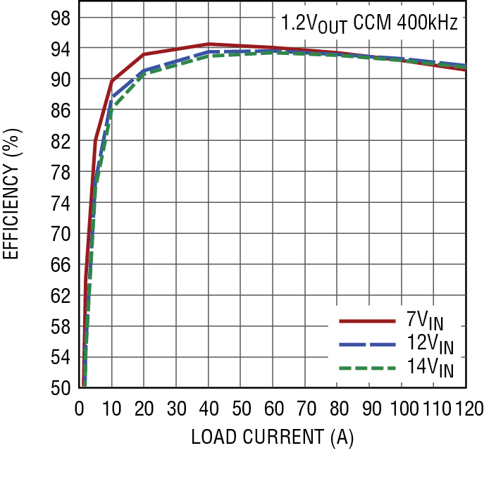
Figure 2: LTC7851 efficiency curves for a 7.0, 12 and 14V input to a single 1.2V/120A output
When multiple LTC7851/-1 channels are paralleled to drive a common load, accurate output current sharing is essential. If one stage is delivering more current than another, then the temperature between the two stages will be different, and that could translate into higher switch RDS(ON), lower efficiency, and higher RMS ripple. A mismatch of even a small amount can greatly diminish the total power available in a multi-phase design. With tight current sharing specifications, designers will be able to extract the maximum output current from today’s DrMOS devices.
For single output, multi-phase applications, an auxiliary current sharing loop samples the inductor current at each cycle. The master controller’s current sense amplifier output is averaged at the IAVG pin. A small capacitor connected from IAVG to GND (typically 100pF) stores a voltage corresponding to the instantaneous average current of the master controller. The master phase and slave phases IAVG pins are connected together and each slave phase integrates the difference between its current and the master. Within each phase the integrator output is proportionally summed with the system error amplifier voltage, adjusting that phase’s duty cycle to equalise the currents. When multiple ICs are daisy-chained, the IAVG pins are connected together resulting in a current imbalance of approximately two to three per cent. Figure 3 shows the inductor current sense voltage for each of the four phases versus load current and how well they balance across the entire load range.
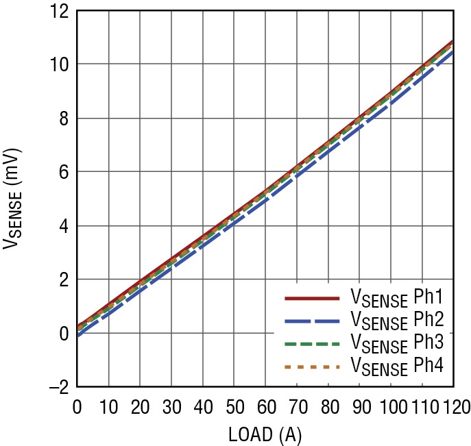
Figure 3: Four Phase Current Balance for a Single 1.2V/120A Output
Multi-phase operation
Up to 12 phases can be daisy-chained to run simultaneously out-of-phase with respect to each other. A multi-phase power supply reduces the amount of ripple current in both the input and output capacitors, which significantly reduces the EMI and filtering required when compared to a single phase alternative. The RMS input ripple current is divided by, and the effective ripple frequency is multiplied by, the total number of phases used. The output ripple amplitude is also reduced by the number of phases implemented. Figure 4 shows how easy it is to hook up multiple devices for three-, four-, eight- or 12-phase operation.
When the LTC7851/-1 is used in a single output, multi-phase application, the slave error amplifiers must be disabled by connecting their FB pins to VCC. All current limits should be set to the same value using only one resistor to SGND. The CLKOUT signal can be connected to the CLKIN pin of the following LTC7851/ -1 stage to line up both the frequency and the phase of the entire system.
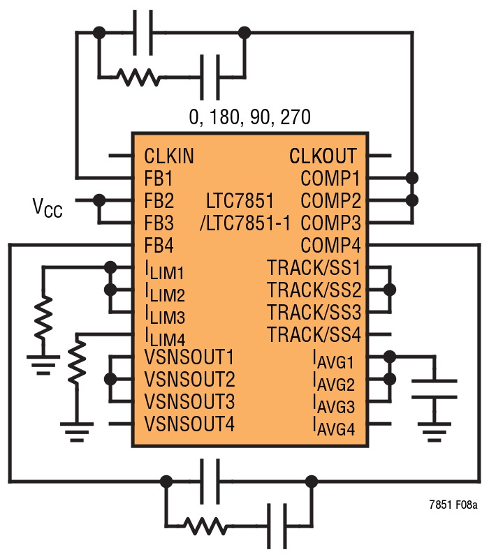
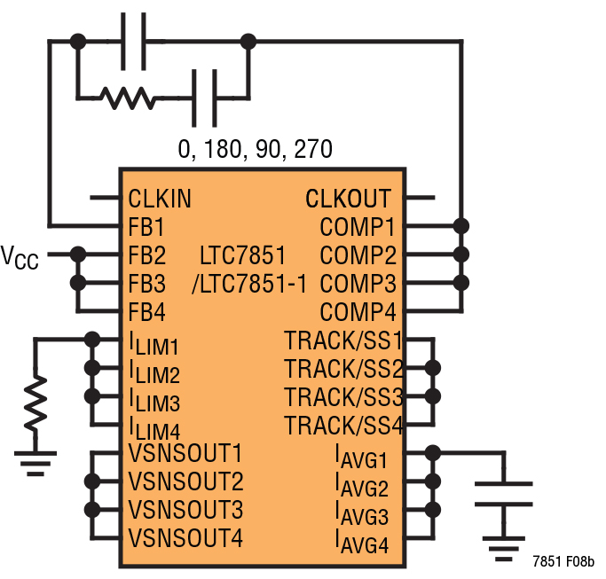
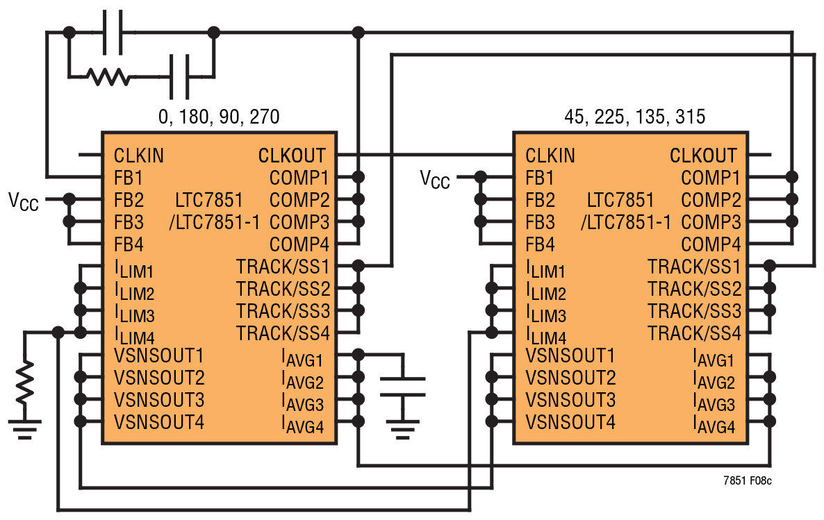
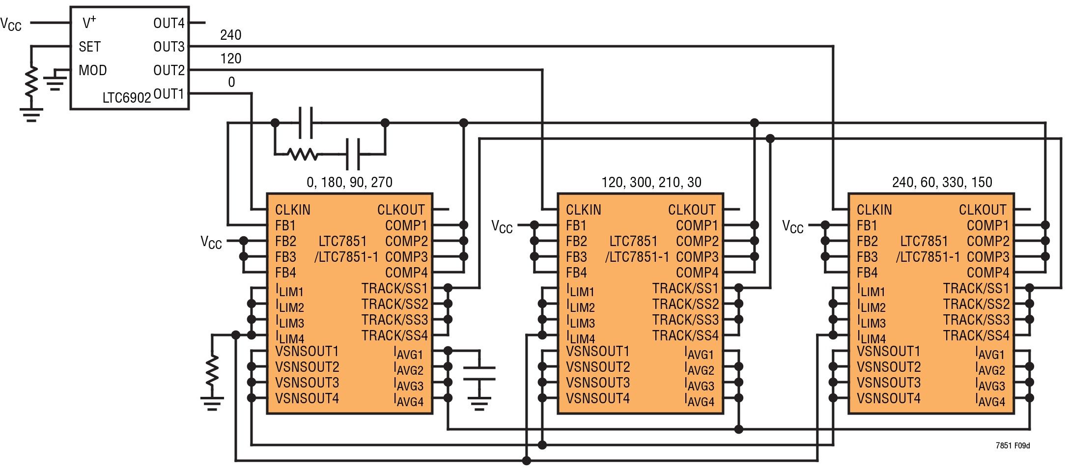
Figure 4: LTC7851 multiple phase configurations
Power system designers can now create designs for increasingly complex router and switch designs, at different power levels, using a single DC/DC controller that scales across multiple platforms. The ability to select from one to 12 phases, at up to 40A/phase along with using DrMOS or power blocks in the power train, provides flexibility for the next-generation of demanding communication and networking products.
Product Spotlight
APV1111GVY
Panasonic

Panasonic PhotoMOS® Photovoltaic MOSFET High-Power Drivers
| SKU: | |
|---|---|
| Stock: | 3490 |
| Cost: | $3.95 |
