
Observing inrush current to avoid power conversion failure
Inverters provide ‘simple’ power conversion but can be susceptible to failure if consideration to inrush current isn’t observed, explains Mehdi Samii, Vice President of Engineering, Ametherm.
Inverters are electrical systems that provide variable voltage (AC output) when connected to a DC input source. Inverters are available in two varieties: three phase and single phase. These inverters are also known as static frequency chargers or variable frequency drives. Inverters experience failure due to inrush current pulses from the grid causing stress on components, such as filter capacitors, which are used as filters to reduce ripple effect. Another common failure of inverters due to inrush current is overloading the inverter. This is due to the fact that most inverters are designed with a minimum amount of resistance in order to increase their efficiency and minimise losses due to heat.
For example, an overload condition will occur if you switch on three appliances - one by one - connected to an inverter. Consider the following: a 1000W inverter (more specifically, a 1500W inverter with 50% total overload capacity) and three standard appliances: a 300W refrigerator, a 300W LCD television and a 300W computer. The total load for these appliances is 900W. A 1000W inverter is fully capable of running the three appliances above, the overload condition happens because of energy required for start-up. This inrush current can produce up to 900W, or 3 times the rated power, for each appliance. The inverter overloads in the following scenario:
Step 1: If we switch on the first appliance, the load is 900W, which is less than the rated capacity of the inverter. Thus, no overload situation is encountered.
Step 2: If you switch on the second appliance, the total wattage needed is as follows: first appliance (300W) + second appliance (900W) = 1200W. No overload situation is encountered
Step 3: If you switch on the third appliance, the total wattage needed is as follows: first appliance (300W) + second appliance (300W) + third appliance (900W) = 1500W
Notice that an overload condition is encountered as soon as the third appliance is switched on to the inverter. See (a) of Figure 1.
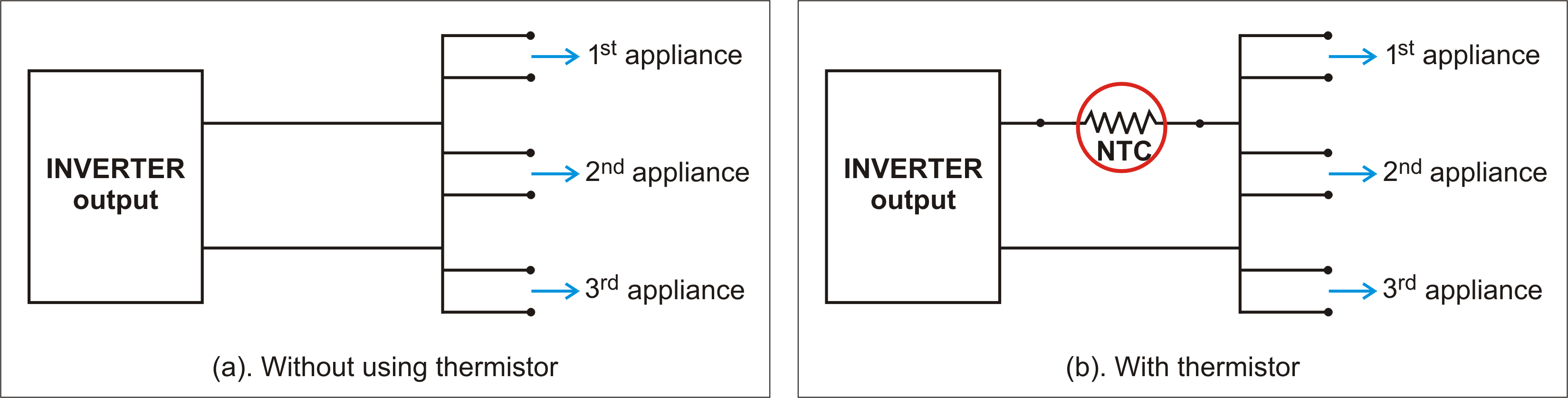
Figure 1 - Circuit configuration with and without a thermistor
Possible solutions
A thermistor (see Figure 1(b).) can be used to address the overload scenario of the sample problem. As per Step 3 above, the inverter wattage needed, including the overload condition, is less than 1500W. The max output power allowed is 1000W, while the allowed current is 8.0A (1000W/120V). The normal continuous current per appliance is 2.50A (300W/120V), and 7.50A due to inrush current (2.50A x 3). The duration of the inrush is 0.02 sec (one cycle = 1x1/50 sec). The energy of the thermistor needs to handle without self destruction is 18.0J (120Vx7.50A for 0.02 sec). So, for three appliances that start up at the same time, 54J is needed (3x18.0J). A minimum resistance of 21.21Ω (peak voltage/maximum allowable current: 120Vx1.414/8.0A) ensures that the current does not exceed 8.0A. So if we assume an ambient temperature of 50°C and minimum resistance of 40Ω, we can reconnect. There are two methods for solving this situation.
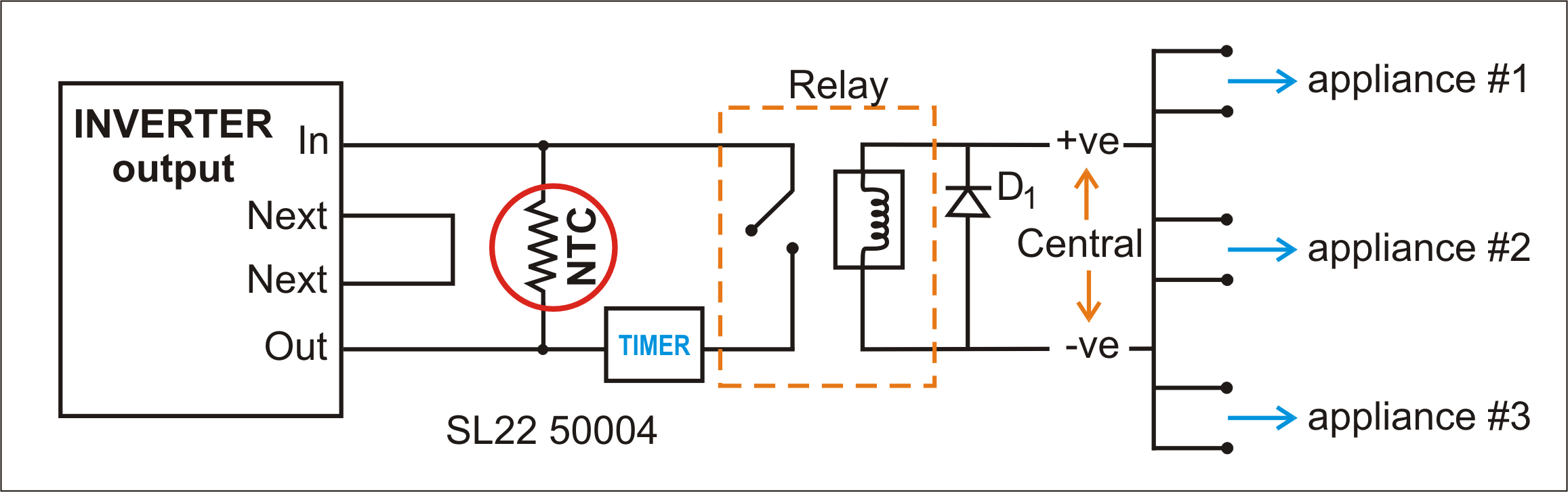
Figure 2 - Surge protection using a single NTC thermistor
In the circuit shown in Figure 2, a 50Ω, 4.0A, 75J NTC (UL recognised (E209153) and CSA recognised (CA110861) is used to bypass the surge after one second. Note that the NTC does not interfere with the efficiency of the inverter, since the relay is also protected from the inrush current by the thermistor. The thermistor will conduct through the relay with 99.2% efficiency.
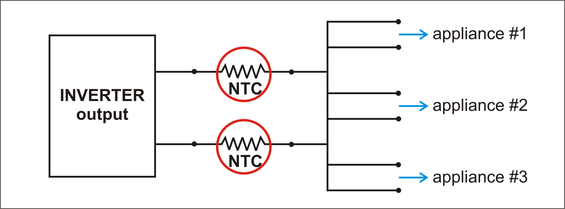
Figure 3 - Surge protection using two NTCs thermistor
In Figure 3, two 40Ω, 10A, 500J NTCs are used. An analysis shows that method B is more cost effective. Simple NTC thermistor applications are shown in Figures 4 to 6. These thermistors minimise the effect of inrush current on components, such as bridge or link capacitors.
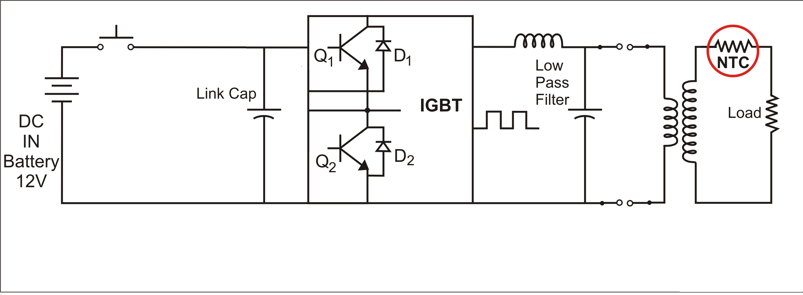
Figure 4 - Classic inverter circuit
The application shown in Figure 4 involves an inverter powered by 12V, 40A battery input and 120V 4A output. The peak inrush current as measured on the oscilloscope is 400A, due to the low impedance of the inverter. The frequency is 50Hz. The following values can be calculated:
Inductive reactance (XL) = input voltage / inrush current: XL=12 V/400A = 0.03Ω
Inductive reactance (XL) also = 2πfL, where f = frequency and L = inductance: 0.03Ω = 2*(3.14)*50Hz*L (L = 95.5µH)
Energy (E) the thermistor needs to handle without self-destruction = ½ LI2, where L = inductance and I = peak inrush current: E = ½(95.5*10-6)(400A)2 = 7.64J
Steady state current rating = I: Pout of transformer = Pin of transformer: 120 V*I = 12V*40A, I = 4A
Minimum resistance required = Vpeak / max tolerable inrush current (assume max tolerable inrush current =1/4th of the maximum measured): 400A*¼ = 100A max; Minimum resistance = 12V/100A = 0.12Ω
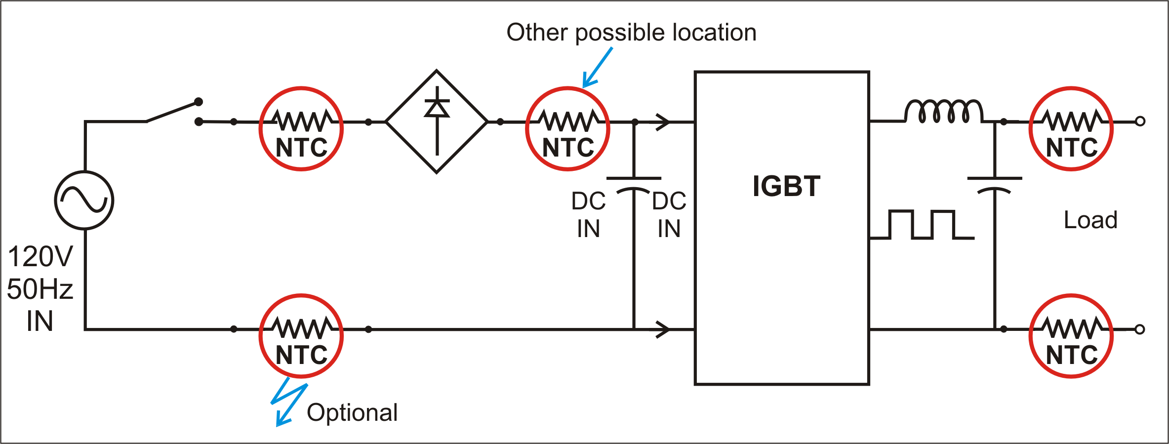
Figure 5 - Frequency Charger
Since thermistors are temperature dependent, care must be taken to select the correct part. Assume the ambient temperatures is 50ºC. For most NTCs, the resistance at 50ºC is half the resistance at 25ºC. So the correct minimum resistance for this application would be 0.24Ω (2*0.12Ω). For safety purposes, select a thermistor with a higher steady-state current rating than 4A and double the energy rating.
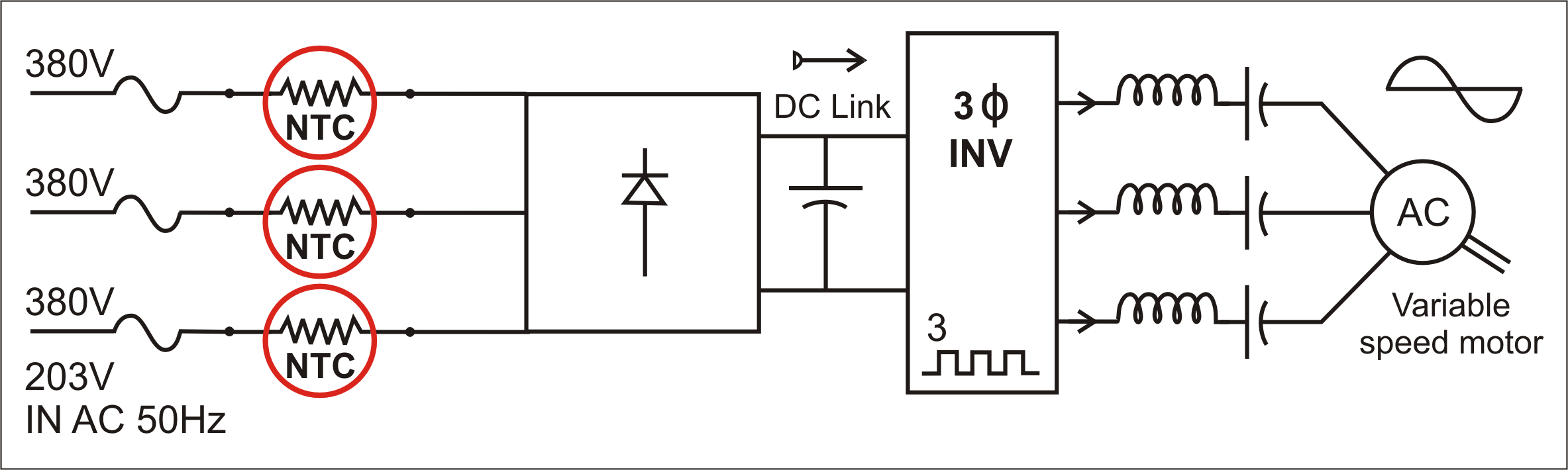
Figure 6 - Variable Frequency Drive
Product Spotlight
APV1111GVY
Panasonic

Panasonic PhotoMOS® Photovoltaic MOSFET High-Power Drivers
| SKU: | |
|---|---|
| Stock: | 3490 |
| Cost: | $3.95 |
