
A motor driver with a bridge to a wonderful heritage
If you’re into cars you’ll be able to run-off a list of classic, iconic vehicles that were pivotal in automotive history. The same goes for aviation, with quintessential designs being memorable for their shape, role or performance. Compared to these sectors, semiconductors are a fledgling industry, having only really got started back in the 1950s. Some 70 years into its history, now is a good time to reflect on our history in order that we recognise the greats of our industry too. Sven Hegner, Chief Engineer at Toshiba Electronics Europe, explains.
Products that have really changed the world and captured the imagination are the ones about which entire books are written, and the semiconductor industry is no different. They include a range of standard integrated circuit designs that many electronics engineers with multiple decades of experience will have touched or been influenced by during their training, or even before as children exploring this exciting world.
If you were building any sort of timing circuit, you probably used the NE555. This 8-pin device offered monostable, bistable, and astable operational modes with larger devices allowing these capabilities to be combined thanks to having multiple 555s on a single chip. The analogue gurus amongst us will have poured over amplifiers and filters built around the µA741, designed once and copied many times by most of the big name players. And who hasn’t turned to the 7805, in one of its many variants, to build a 5V power supply?
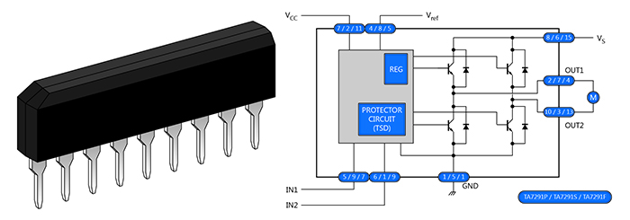
Above: Figure 1. The SIP package and block diagram for the TA7291 H-bridge controller
Of course, these devices emerged from the North American semiconductor industry. However, the Japanese semiconductor industry also has its own iconic designs with rich histories. One such device is the TA7291 H-bridge motor controller (Figure 1).
The video cassette recorder (VCR) enabled television programmes to be recorded, edited, and then broadcast at a time of the broadcaster’s choosing – a big shift from having to transmit everything live. Initial implementations were developed in the mid-1950s but devices targeting everyday consumers started to appear in the 1970s.
The plastic cassette needed a mechanism to take in and eject the media, requiring motor control electronics that could operate bi-directionally. Toshiba developed the highly integrated TA7291 to address this and related applications, enabling several transistors and other components to be embedded into a single device. Since then, the TA7291 has attained cult-like status, being honoured in a number of books alongside Raspberry Pi and Arduino boards to demonstrate how to implement H-bridge motor control.
The basics of H-bridge motor control
When learning about motor control, the basics of using a transistor or MOSFET coupled with a microcontroller to start and stop a DC motor are quickly understood, along with speed control using a pulse-width modulated (PWM) output. However, forums and maker websites are often full of questions around bi-directional motor control and its implementation with a H-bridge.
A H-bridge is essentially four switches that allow the polarity of the supply applied to a motor to be attached both ways round (Figure 2). Thus, the motor can be driven both clockwise or counter clockwise. It consists of a pair of high- and low-side switches with the motor connected between the two pairs. The engagement of the switches has to be carefully implemented as enabling a high- and low-side pair results in a short-circuit of the power source, something that rarely ends well. Therefore, the designer has to ensure that only a diagonally opposed pair of high-/low-side switches can be engaged at any moment in time.
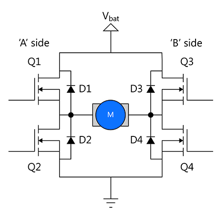
Above: Figure 2. Circuit diagram for an H-bridge showing the free-wheeling diodes and motor
The switches can also be used to implement an electronic braking mechanism. When the rotor is spinning, the motor acts as a generator creating what is known as back-EMF (electromotive force). By shorting the motor terminals together, either by enabling both high-side or low-side switches, the energy can be used to slow the rotor down more quickly. It should, however, be noted, that this braking only functions when the rotor is moving and does not fulfil the function of a mechanical brake.
The back-EMF is an issue for the switches when they are off as the voltages generated can damage them. In order to protect them, diodes, known as free-wheeling or flyback diodes, are placed in parallel to the switches. These provide a current path for these voltages when the motor is spinning down. One of the advantages of an integrated H-bridge device is that all of these elements are integrated into a single chip, thereby saving space on the circuit board.
Next generation H-bridge technology
The TA7291 has been on the market for over 40 years, with roughly ten million units being consumed per year. However, new fabrication processes mean that lower on-resistances (RDS(ON)) for the switches can be achieved, along with support for higher powers and new protection mechanisms. This has led to the development of two new H-bridges, the TB67H450FNG and TB67H451FNG, that take the best of the past and marries it with the benefits of the latest BiCD silicon process (Figure 3). They also handle more current and higher voltages than their predecessor.
The industry standard pin-out in an 8-pin SOP package also means that the devices can be used as part of a multi-sourcing strategy, if required.
The power stage has been upgraded from bipolar transistors to MOSFETs that have a typical RDS(ON) of just 0.6Ω (high-side plus low-side). Pre-drivers are integrated along with charge pumps, as is the control logic and voltage regulator, allowing the device to be powered from a single pin. The upper operating limits are now 3.0A and 44.0V operating voltage.
Basic control is much the same as its predecessor with two digital pins available to define rotation direction and apply braking. This ensures that the bridge cannot be placed in a mode that short circuits the power supply. A STOP mode places the device into standby whereupon the device consumes just 1µA of current. This mode is also used to reset various protection mechanisms, should they trip, such as the over current monitoring on the TB67H450FNG. This trips once the current drawn rises above 4.9A. On the TB67H451FNG the over current protection clears automatically.
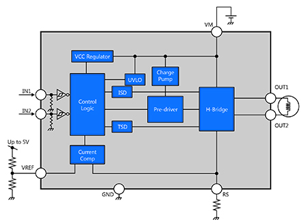
Above: Figure 3. Block diagram of the TB67H450FNG and TB67H451FNG with their compact, 8-pin design
There is also an under-voltage lock-out (UVLO). This kicks-in at 3.8V, shutting down operation until the supply rises above 4.0 again. For those looking to build a simple USB-powered application, this provides excellent protection.
PWM control can be implemented via the digital control inputs with frequencies of up to 400kHz supported and minimum pulse widths of 500ns. Overheating is also kept in check with the device shutting down once a junction temperature of around +160°C (typical value) has been reached.
The hysteresis on this mechanism is +30°C. Finally, constant current mode motor control can be implemented if desired.
Evaluation of both devices is simplified thanks to new development boards such as the DC Motor 14 Click from MikroElektronika (Figure 4). Utilising the standardised pinning approach of their mikroBUS boards, they also offer a driver as part of their mikroSDK software package, allowing the device to be tested quickly and efficiently.
Summary
As in all things, the basics still apply and the many brushed motor control applications on the market today continue to demand highly integrated H-bridge solutions. As fabrication processes improve it makes sense to move to silicon technologies that also bring higher levels of integration and the associated improvements, such as higher energy efficiency and enhanced robustness. The TB67H450FNG and TB67H451FNG build upon a fantastic semiconductor heritage and we hope that it will also contribute in launching the careers of as many future engineers as the TA7291 did.
Product Spotlight
APV1111GVY
Panasonic

Panasonic PhotoMOS® Photovoltaic MOSFET High-Power Drivers
| SKU: | |
|---|---|
| Stock: | 3490 |
| Cost: | $3.95 |
