
Sigma-delta modulators aid motor control
How to achieve fast, accurate over-current detection using optically coupled sigma-delta modulators, by Wong Chee Heng and Lim Shiun Pin, Broadcom
In an industrial motor control system, sensing and feedback of parameters such as motor phase, DC bus current and voltage, torque, direction and speed, are required for proper operation of the system. As systems move towards higher precision, power, speed, multi-axis, and multi-directional motors, these requirements become increasingly important. As the motor encoder measures the torque, speed, and direction, the sigma-delta modulator provides high accuracy, high linearity, wide dynamic range, fast-response current, and voltage sensing. Traditionally, current sensing is done by using current transformer or a Hall-effect sensor, but these are bulky, expensive, and less accurate over operating temperature. A smaller, low-cost current sensing option can be realised by directly connecting a shunt resistor to the sigma-delta modulator. Phase current flows through the shunt resistor with a resistance value selected such that the maximum current range corresponds to an optimum low voltage of about ±50mV at the input of the sigma-delta modulator. At this low voltage, power dissipation loss across the shunt resistor is minimised. Figure 1 illustrates the phase current sensing and DC bus voltage and current sensing of a sigma-delta modulator in a motor control system.
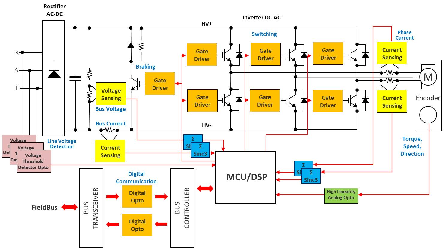 Figure 1: Sigma-delta modulator used in output phase with DC bus voltage and current sensing rectifier
Optical coupling
One of the most expensive devices in a motor control system is a power semiconductor switching device like the IGBT or power MOSFET. Switching at high frequency, these power devices introduce unintended noise and high-voltage transients across the control system. The high-frequency transient may affect the normal operation of the sensitive, expensive microcontroller. Sigma-delta modulators, in combination with superior optical coupling isolation technology, deliver high noise margins and excellent immunity against isolation mode transients. With a minimum distance through insulation (DTI) of 0.5mm, these sigma- delta modulators provide reliable double protection and a high working voltage suitable for failsafe designs. This proven isolation performance is superior to magnetic or capacitive-based isolators, where DTI is only a third of 0.1mm.
Sigma-delta modulators convert the analogue input signal into high-speed single-bit data streams by means of a second-order sigma-delta over-sampling modulator. The average time of the modulator data is directly proportional to the input signal voltage.
Broadcom’s ACPL-796J and ACLP-C799 optically isolated sigma-delta modulators are two types of sigma-delta modulators, based on whether the clock source is internally built-in or externally provided to the modulator. For the internally clocked type, a 10MHz clock is built in at the primary side of the isolation barrier where the sigma-delta encoder is located. The clock signal is encoded together with the data and coupled across the isolation barrier to the secondary side of the isolation barrier where the clock and data signals are decoded. The externally clocked- in type receives the clock signal at frequency ranges from 5.0 to 25MHz at the secondary side. It is then coupled across the isolation barrier to the primary side. At the secondary side of both types of modulators, data is decoded into a high-speed data stream of digital ones and zeros. Figure 2 illustrates the simplified block diagrams of internally and externally clocked sigma-delta modulators.
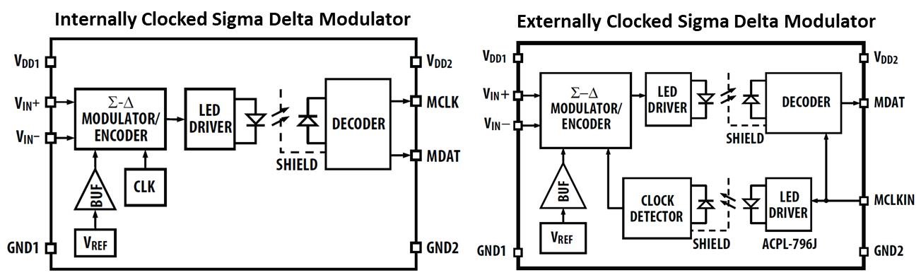 Figure 2: Schematics of internally and externally clocked sigma-delta modulators
Original analogue input information is represented by the density of digital ones or zeros at data output. The modulator data received on the isolated side is then sent to a processor for filtering and conversion. A decimation filter can be implemented on an FPGA or microprocessor to recover the desired signal. The decimation filter averages or decimates the high-speed over-sampled bit stream to a lower rate by a factor commonly known as decimation ratio. By selecting a higher decimation ratio, better resolution of the recovered data can be achieved at the expense of longer filter delay time.
Over-current detection
Over-current or short-circuit conditions in an IGBT can occur due to a phase-to-phase short, a ground short, or a shoot through. Typically, an IGBT can survive short-circuit conditions up to 10µs before failure. Within this time period, a fault must be generated as feedback to the microcontroller to trigger an immediate shutdown procedure within the system.
One method is to detect the over-current directly from sensing the phase current using the sigma-delta modulator. Usually, a longer post-processing time of the sigma-delta modulator output data is required to achieve higher resolution of the measured phase current. As a result, over-current may not be detected quickly enough to shut down the entire control system.
One implementation uses two filter paths, one with a decimation ratio of 256 for higher resolution and another with a decimation ratio of 32 for fast over-current detection. A typical application using a 20MHz clock frequency requires about 12.8μs filter delay time with a decimation ratio of 256 and 1.6µs with a decimation ratio of 32. Besides the filter delay, an additional 0.5μs must be considered for the sigma-delta processing and for latency across the isolation barrier. To shorten the response time further, a simple fault-detection logic block can be used in place of the low decimation ratio filter. This method detects a pre-programmed continuous n-bits of one or zero directly from the data output of the sigma-delta modulator without going through further processing or conversion (see Figure 3 and Figure 4).
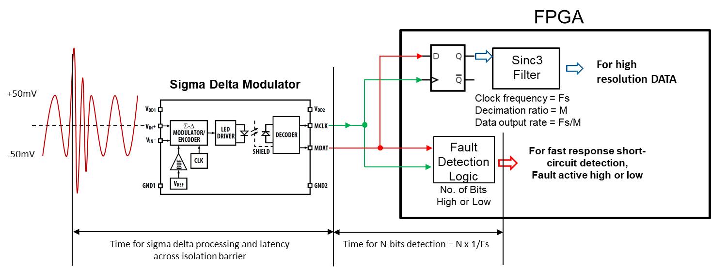
Figure 3: Output data of the ACPL-796J connected to separate paths inside the FPGA (for high-resolution conversion and fast response detection)
Fault detection logic can be easily implemented in an FPGA or microcontroller. One method is to implement an n-array of D-type flip-flops. The outputs of the array of flip-flops are connected to an AND gate for n-bits high detection and to a NOR gate for n-bits low detection. When the first bit of a stream of continuous high or low bits reaches the last flip-flop, the AND gate output turns logic high for continuous n-bits logic 1 (high). Similarly, the NOR gate output goes high when continuous n-bits logic 0 (low) are detected. This provides fault feedback to microcontroller.
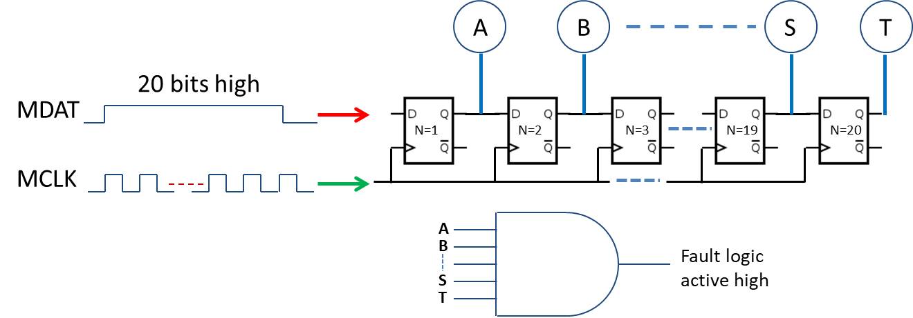
Figure 4: Output data of the ACPL-C799 connected to separate paths inside the FPGA
Table 1 shows the densities of bit 1 and bit 0 are proportionate to the voltage level at the input of the sigma-delta modulator. A continuous stream of 20b logic 1 is detected at an input voltage level of +270 mV for the ACPL-796J and +63mV for the ACPL-C799. Likewise, a continuous 20b logic 0 is detected at -270 mV for the ACPL-796J and -63 mV for the ACPL- C799. If a shunt resistor is selected such that an optimum recommended input voltage of ±200mV / ±50 mV is measured at the input of the sigma-delta modulator corresponding to a target-measured current range, then a stream of continuous 20b high or low will not be present at the output during the normal condition. However, when there is an over-current event, the input voltage rises immediately beyond the default voltage level. By then, a continuous stream of 20 or more high or low bits is sent out from the sigma-delta modulator output. The fault detection logic captures this output data and triggers a fault signal immediately within 1.54μs (for the ACPL-796J) or 2.52μs (for the ACPL-C799) from the start of the over-current event.
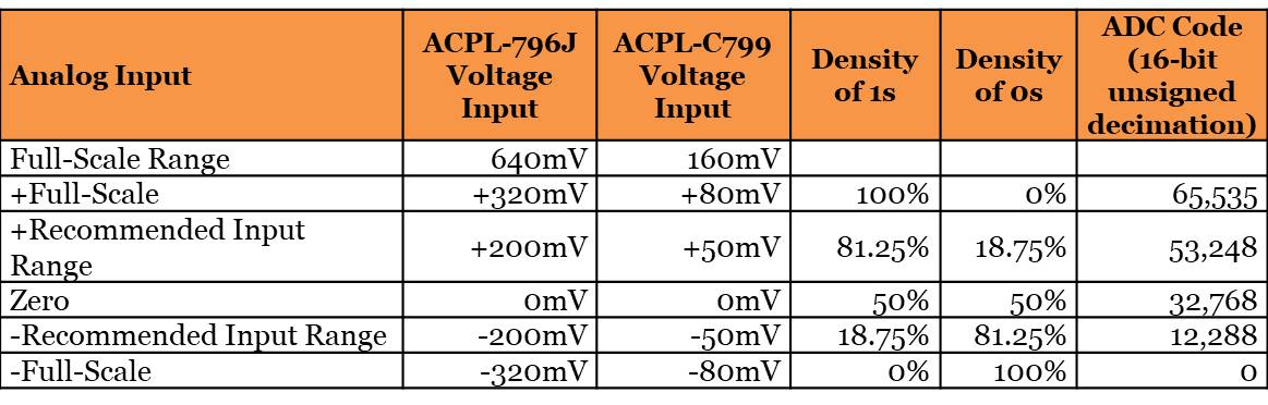 Table 1
For the ACPL-796J, a further reduction of response time to sub-1µs can be achieved if the input voltage range of the sigma-delta modulator is optimised to ±50mV. When an over-current event occurs, the input voltage level goes beyond ±100mV which corresponds to 5b continuously high or low at the sigma-delta output.
For the ACPL-C799, a further reduction of response time can be achieved if 15b or 10b detection is used. However, a smaller input operating range results in a lower signal-to-noise ratio during normal operation.
Table 2 shows various configurations of n-bit detection versus response time and the suggested normal operating input range.
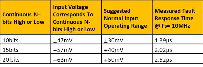 Table 2
The fast shutdown of the motor control system during an over-current event prevents catastrophic damage to the expensive power semiconductor switching devices. Optically coupled sigma-delta modulators not only provide high-resolution current measurement with proven and reliable fail-safe isolation protection, but additional fast-response over-current fault detection functionality can be easily implemented by feeding the single-bit stream output data directly to a simple bit-stream detection circuitry. This can be accomplished without having to change hardware configuration or increase the component count.
Product Spotlight
APV1111GVY
Panasonic

Panasonic PhotoMOS® Photovoltaic MOSFET High-Power Drivers
| SKU: | |
|---|---|
| Stock: | 3490 |
| Cost: | $3.95 |
